In this post you will find the description of a graphic display that uses a modular solution based on dot matrix blocks (in which each dot is a RGB LED), that are driven – via a specific bus – by a very powerful control board, that is entirely programmable and capable of managing even very fast animations, thanks to the FPGA it is supplied with. Yes, the key factor is the Spartan-6 Field Programmable Gate Array by Xilinx, that is able to execute programs at very high speed, thanks to its parallel processing capability (multi-thread); the model that has been used in the project was chosen because it represents the most performing FPGA available on the market as a TQFP package, therefore it may still be soldered by means of the traditional tools. In order to create our modular display we are using a control board that will be described in the next pages; actually it is not limited to the said application, but it’s a generic and very powerful and versatile controller, whose advantages and the usage possibilities you will understand better in the next paragraphs and in the future articles. The displaying part is on the other hand composed by RGB LED dot matrices supplied with a shift-register; the whole will enable the management of a giant display with a 320×240 pixels resolution, each pixel is characterized by a 256-colour True Color definition at a 25 Hz refresh frequency, that is more than enough to show flicker-free moving pictures.
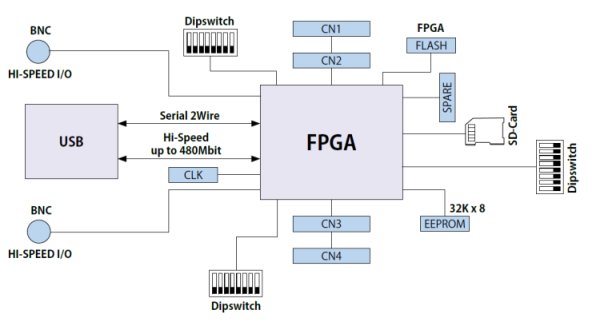
We will deal with the displays later on, since now it is the case to focus our attention on the controller board, that is a very powerful and versatile development board, based on a Spartan 6 FPGA XC6SL9; 62 out of its 102 I/Os are available for a generic usage, while the remaining ones have been assigned to dedicated functions such as the USB serials, the EEPROM memory, the SDcard, the Boot Flash, etc. Even though it is here used as a display controller, it may help you realize an infinity of applications.
We coupled a Winbound Flash memory (signed as 25Q64FVSIG) to the FPGA, it will be the FPGA’s boot memory: a bootloader (that remarkably simplifies the programming) resides in it, and even 16 firmwares may be stored (thanks to the bootloader itself) by taking advantage of the possibility to store 16 slots for the bitstreams (the FPGA programs are thus called); out of the 16 slots, one (number 0) has been fixedly assigned to the bootloader, and the other 15 to the programs. The bitstream to be booted is chosen from the bootloader’s menu and directly from the terminal. The Flash memory is a 64 Mbit access serial one, that has been implemented thanks to dual/quad SPI configurable links.
Read more: A FPGA controlled RGB LED MATRIX for Incredible Effects