1. Introduction & Background Theory
1.1 Objective
The objective of this project is to research, analyze, design, fully implement, and program an Arduino Uno microcontroller board to achieve PI control of the output power of a laser diode. Laser diodes require variable current sources for operation, as the current must be adjusted to maintain linear output.
First conceptualized in the 1960s, lasers have become essential in modern technology, finding applications in various products such as image scanning and printing, laser pointers, barcode readers, fiber optic communication signals, and reading information on CDs, DVDs, and Blu-ray discs. The ubiquity of lasers in today’s technology cannot be overstated. Despite their efficiency and versatility, laser diodes are complex devices. Their operation involves specific characteristics that make them applicable to numerous fields but also present challenges in their use. A typical laser diode cannot function with a constant voltage source alone; thus, driver circuits are necessary to manage and control their output.
1.2 System Outline
For this project, an Arduino Uno microcontroller will be used to control a laser diode. The project entails completing tasks outlined in the project brief, such as understanding the principles of PI control and laser diodes, implementing a PI control loop on an Arduino board, designing a current source and optical detector, and testing with a visible laser diode. The goal is to operate a semiconductor laser diode by using the Arduino Uno to monitor the diode’s output power and perform proportional-integral control of the input voltage to maintain a constant current flow through the diode.
This project integrates hardware circuit design—implementing a circuit to perform tasks required by the Arduino microcontroller—with software design, involving the creation of a program to achieve the stated objectives. This aligns well with the modules I am studying this semester, which are part of the General stream in the LM118 Electronic and Computer Engineering course. The project’s blend of hardware and software elements will provide valuable experience in both the physical and practical aspects of engineering, relevant to both sectors. Having had little to no prior experience with microcontrollers, this project offers an exciting opportunity to explore the capabilities these devices afford.
2. Analytical Background
2.1 Arduino
Arduino Uno
Arduino is an open-source prototyping platform that can be best described as a single-board computer, featuring user-friendly hardware and software. The name ‘Uno,’ meaning ‘one’ in Italian, reflects its origin, with Massimo Banzi being one of the key inventors of this tiny yet powerful open-source microcontroller. Despite its compact size, the Arduino is remarkably powerful, offering computing capabilities comparable to one of the original Apollo navigation computers, but at a fraction of the cost—approximately 1/35,000th.
Arduino boards can read inputs, such as light on a sensor or heat on a thermistor, and convert them into outputs, such as activating a motor or LED. The open-source Arduino software (IDE) facilitates easy code writing and uploading to the board, and it is compatible with Windows, Mac, and Linux. The development environment, written in Java, is based on Processing and other open-source software, making it versatile and accessible for various Arduino boards.
Programs running on Arduino are called sketches, consisting of two main parts: setup() and loop(). The setup() function configures the board’s initial state, defining which pins serve as inputs or outputs and setting up any special output devices like a four-character display. It also handles communication settings if interacting with external devices via serial ports or Ethernet connections. The loop() function continuously processes the input and output, ensuring the Arduino executes the instructions repeatedly without stopping. Below are some technical specifications of the Uno board [20]:
| Microcontroller | ATmega328 |
| Operating Voltage | 5V |
| Input Voltage (recommended) | 7-12V |
| Input Voltage (limits) | 6-20V |
| Digital I/O Pins | 14 (of which 6 provide PWM output) |
| Analog Input Pins | 6 |
| DC Current per I/O Pin | 40m A |
| DC Current for 3.3V Pin | 50m A |
| Flash Memory | 32KB (0.5KB used by Bootloader) |
| SRAM | 2KB |
| EEPROM | 1KB |
| Clock Speed | 16 MHZ |
Figure 1: Arduino Uno Specifications
PWM on the Arduino
Pulse Width Modulation (PWM) output is available from 6 of the digital I/O pins on the Arduino. PWM allows for generating a variable signal from a fixed signal by altering the width of the pulses, which changes the duty cycle of the waveform.
The duty cycle measures the proportion of time the signal is active. The Arduino can produce PWM signals at a frequency of 490 Hz. For instance, with a 10V signal and a 10% duty cycle, the 10V signal is active only 10% of the time, resulting in an average signal of 1V. A higher duty cycle corresponds to a higher average output signal. By adjusting the pulse width, the average value of the signal changes, enabling control of a load by pulsing its current.
For devices like laser diodes or LEDs that require a DC input, the PWM signal can be filtered to average the amplitude according to the duty cycle percentage, creating a mean DC voltage. This mean voltage can theoretically vary between the high and low values of the PWM signal (±5V).
2.2 Laser Diodes
Introduction
A laser diode, also known as a semiconductor laser or injection laser diode, is a crucial component in optoelectronics. These diodes are utilized in a wide range of modern technological applications, including fiber optic communications, optical sensors, barcode readers, laser pointers, CD/DVD readers, and laser printers. The performance of these systems significantly depends on the modulation and noise characteristics of the laser diode.
The concept of the laser was first introduced by Dr. Schawlow and Townes in 1958, and the first operational laser was built by Theodore Maiman in 1960. While working at Hughes Research Laboratories, Maiman created the first laser that emitted short pulses of red light using a ruby cylinder surrounded by a xenon arc flash lamp, similar to those used in aerial photography. The initial requirements for lasing, established by Schawlow and Townes, were met: “a readily excited fluorescent material of good optical quality, a method for stimulating the material to an excited state, and an optical resonating cavity.” Since then, almost all lasers have followed these principles. Initially, fluorescent crystals like rubies were commonly used, until the gas laser was developed a year later. In 1962, the first semiconductor injection laser was created by Bell Telephone Laboratories.
Laser diodes, once expensive semiconductor components, have now become affordable and are integral to devices with fiber optic requirements. Low-power red laser pointers are readily available for 10-20 euros. Laser diodes typically come in a 3-lead metal package, including an internal photodiode that regulates the output light by adjusting the applied drive current.
Laser diodes can be characterized in five main categories:
- Spectral: Calculated spectral width and center wavelength from acquired spectral data.
- Electrical: Measures of the light output, voltage drop, and current monitored by a photodiode.
- Spatial: The intensity of the light in both far and near fields and the angle of radiation.
- Dynamic: Noise, distortion, rise and fall time, and other dynamic features.
- Optical: Measurement of deviation from spherical curvature and other wavefront errors.
Design and operation
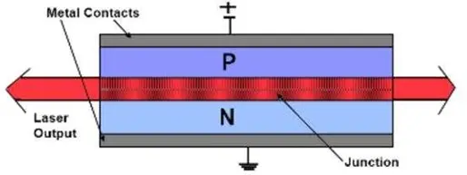
There are various types of laser diodes, but a typical laser diode follows a straightforward design. It consists of two semiconductors layered one above the other. The top layer is made of Gallium Arsenide (GaAs), a P-type semiconductor engineered to have holes that can be filled by electrons. P-type semiconductors are materials that have a tendency to gain extra electrons. The bottom layer is composed of Gallium Arsenide doped with Selenium (GaAs
), an N-type semiconductor that has an extra electron it is inclined to lose.
Between these two layers lies the P-N junction. When current flows through the semiconductors, negatively charged electrons and positively charged holes migrate towards this P-N junction. At the junction, electrons from the N-type semiconductor combine with holes from the P-type semiconductor. Since the hole exists at a lower energy level than the free electron, the electron must release some energy to combine with the hole. This energy is emitted as a photon of light, with the energy of the photon corresponding to the energy difference between the electron and the hole.
The emitted photon is trapped within the P-N junction by mirrored surfaces, which encourages further electron-hole recombination, releasing additional photons. These new photons are in the same phase, polarization, and direction as the original photon, leading to a continuous amplification of light within the junction. As the process continues, the junction fills with coherent light.
Some of this light escapes from the rear of the laser diode, where a photodiode can be used to detect this light and help regulate the voltage applied to the laser. The emitted light from the junction is highly diffracted, so a collimating lens is employed to shape the light into a more typical laser beam.

Issues with powering lasers
Lasers, while compact and efficient, possess characteristics that make them versatile across various fields. However, these same attributes can render them challenging to work with. Unlike simple devices that operate with a constant voltage, laser diodes exhibit complexities. The primary issue arises from the fluctuation in forward voltage as the semiconductor material’s temperature increases, leading to an increase in current flow. Moreover, laser diodes exhibit significant variations in performance from part to part and over temperature.
To safeguard laser diodes from potential damage, they require robust protection against overvoltage and overcurrent. This necessitates regulated current and closed-loop feedback systems to maintain consistent optical power. Furthermore, modulation speed is limited, and the process of converting injection current to light is nonlinear, resulting in distortions in light output. Additionally, due to the quantum nature of light, laser diodes inherently generate noise in their light output.
Since laser diodes lack inherent current regulation, driver circuits are essential to limit current flow and prevent component failure. Careful monitoring of current behavior throughout the circuit is crucial to ensure proper operation and prevent damage to the diode. Moreover, thermal considerations are vital, as the laser’s optical power increases with decreasing temperature, necessitating optical feedback to regulate the diode’s output power.
A common approach to driving laser diodes involves using a constant current source circuit. In such circuits, components like the LM317 adjustable voltage regulator are employed to regulate the current. Despite its effectiveness, this design can be inefficient due to the high resistor values involved.
In summary, while laser diodes offer immense potential, their operation requires careful consideration of various factors to ensure optimal performance and prevent damage to the components. Below is an example of a constant current source circuit utilizing an LM317 adjustable voltage regulator, demonstrating one method of achieving stable current regulation.

Design Specifications of the Laser Diode
The maximum ratings and Electrical characteristics of the laser diode for proposed implementation are listed below [5]:

2.3 Current sources
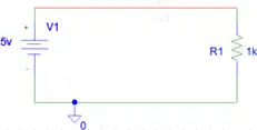
In its simplest form, a current source delivers a consistent current across a load by establishing a corresponding voltage across it, as determined by Ohm’s Law (I = V/R). A straightforward illustration of this concept involves a voltage source connected in series with a resistor, through which current flows.

Theoretically, the current remains constant, calculated as I = V/R. When the load remains consistent, a stable current can be achieved using a constant voltage source.
An ideal current source maintains a consistent level of current regardless of the impedance it’s driving. The direction of the current flow is dictated by the polarity of the driving voltage. The load can include capacitive elements, as capacitors charge at a constant rate. Another example of a current source is a transistor-based circuit, such as one employing a PNP transistor. In such a setup, current flows once the base voltage exceeds 0.6V, resulting in an approximate load current calculation of IL = (Vb – 0.6V)/Re.
When dealing with varying loads, a stable current can be ensured through a constant current supply, also known as an “ideal current source.” These sources adjust the voltage across the load to maintain a steady current level. While ideal current sources are utilized in scenarios requiring consistent power supply or to drive components incapable of regulating their current, there are also methods involving component selection and circuit design to regulate current.
In industrial settings, a constant current source functions akin to a power generator with a significantly higher internal resistance compared to the load. This high internal resistance allows the current supply to remain stable despite load fluctuations. Consequently, current flows along the path of least resistance, favoring the external load over the internal resistance. This behavior is evident in a simple current source powering two resistors in parallel, where the majority of the current flows through the lower resistance path.
Current sources can be categorized into independent types, delivering a constant current, and dependent types, supplying current proportional to another voltage or current in the system. The internal resistance of an ideal current source is infinite, and one with zero current behaves like an open circuit. The compliance voltage determines the output voltage range within which a current source operates effectively. For a transistor-based current source, compliance is set by the range in which the transistors remain in their active region.
In contrast to voltage sources, which maintain constant output voltage as long as the current draw remains within their capabilities, current sources deliver a steady current as long as the load impedance is sufficiently low.
2.4 PI Control
Control Systems theory
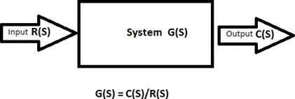
At its core, a control system refers to a system that governs the behavior of another system. It encompasses a set of interacting components within a defined boundary, allowing us to focus solely on inputs and outputs without delving into intricate component interactions. A control system emerges when multiple elements are combined in a specific manner to yield a desired outcome. The primary focus in control systems lies in understanding the relationship between input and output.
Studying systems through this lens offers the advantage of recognizing similarities in output-input relationships across various systems. While each system may possess its unique characteristics, many share comparable input-output relationships. Hence, by analyzing systems with analogous input-output patterns, we can identify different configurations of the system that exhibit similar responses. Additionally, in certain scenarios, systems can be deconstructed into a series of subsystems.

There are two fundamental types of control systems: open-loop systems and closed-loop systems. In an open-loop system, the output remains unchanged despite varying conditions. Open-loop control operates without feedback to the system; in other words, there is no feedback loop. Systems controlled by preset timing mechanisms exemplify open-loop systems. While relatively straightforward in design and cost-effective, open-loop systems may lack accuracy due to the absence of error correction.
In contrast, a closed-loop system incorporates feedback from the output to the input, enabling adjustments to maintain a constant output regardless of changing conditions. According to DIN 19226, closed-loop control involves continuous monitoring of a variable (the controlled variable), comparing it with a reference variable, and adjusting it accordingly to align with the reference variable. This adjustment occurs within a closed loop, where the controlled variable influences itself continuously. Closed-loop systems are typically more intricate than open-loop systems but offer greater accuracy by aligning actual values with required values.
However, closed-loop systems may encounter issues such as delays, which can lead to corrective actions being executed too late, resulting in oscillations and instability.
Proportional-Integral Control
In control systems, the dynamic response of the system is often assessed through its step response. This response entails measuring the controlled variable following a step change in the manipulated variable, determining the behavior that guides the selection of an appropriate controller system. Controllers are instrumental in fine-tuning and modeling specific system characteristics, aiming to reduce steady-state errors and enhance accuracy. Improved steady-state accuracy generally correlates with increased stability, as controllers also help mitigate offsets and noise signals and manage maximum overshoot in a system.
Controllers compare the controlled values with desired values and correct any deviations through predefined functions. Various types of controllers are employed in control systems, including Proportional (P) controllers, Proportional-Integral (PI) controllers, and Proportional-Integral-Derivative (PID) controllers. This project will primarily explore the application of Proportional Integral control, either individually or in combination with other controller types.
While the derivative mode is seldom utilized in isolation, combinations like P, PI, PD, and PID controllers are common. P controllers may not suffice to stabilize higher-order systems, particularly those with multiple energy storage units or first-order processes, where a substantial gain increase can be tolerated.
Proportional Integral (PI) controllers integrate both Proportional and Integral control components. Their output is the sum of the proportional error and the integral of the error signal. Proportional feedback control is defined as:
Where e= error and Kp= proportional gain. Integral feedback is designed as:
Ki is the integration gain factor. So controller out put for a PI controller is:
The Integral mode of the controller serves to continuously sum the controller error e(t)e(t) over time. Utilizing a proportional mode offers advantages such as eliminating forced oscillations and reducing steady-state error. However, the Integral mode can negatively impact response speed and overall stability. PI controllers do not enhance response speed but rather combine the features of P and I controllers. By reducing steady-state error, PI controllers enhance system stability. In cases of slow response in an overdamped system, a PI controller can expedite it while exhibiting maximum overshoot and settling time akin to a P controller.
Commonly employed in industrial settings where response speed is not critical, PI controllers have drawbacks such as producing offset and increasing the maximum overshoot of the system due to proportional control. Integral control, while addressing steady-state error, can decrease stability by responding slowly to generated errors. They find application where rapid response is unnecessary, in the presence of significant disturbances and noise during operation, when significant transport delay exists, or when the process comprises only one energy storage element (capacitive or inductive).
Follow this link for complete project: Arduino microcontroller based laser diode controller

