My Idea
Whenever I go for a run, it bothers me to carry my phone just to track my activity. Those arm bands people use to hold their phones seem awkward to me. If you want to track your runs without carrying a phone, you need a device with dedicated GPS, like Garmin running watches. But the cheapest GPS devices cost around $170. However, GPS technology is available for less than $25, making it more accessible than you might think. One scenario I envision is for high school track or cross country teams, where everyone wants a running watch but only a few can afford it.
For my final project, I aim to develop an extremely portable and affordable GPS watch. It can be used for running, cycling, or simply to track your location openly. Connecting the device to a laptop will facilitate data extraction, enabling uploads to platforms like Strava.
Picking Parts
GPS module
After scouring numerous online platforms, I found that Aliexpress offers a wide range of inexpensive components, typically priced around $5. However, there are drawbacks such as extended shipping times of up to a month and limited data support.
Seeking advice from classmates, one student enthusiastically recommended Adafruit’s Ultimate GPS Module, priced at $29.95 each before shipping costs. With the application of a $5 coupon code, I purchased two modules. What makes these GPS modules exceptional is the extensive support available for them. They come with an Arduino library that simplifies logic implementation, along with a Python module for effortless data parsing. Moreover, the module’s weight is remarkably light at only 4 grams, a stark contrast to the bulky typical GPS watches weighing well over 70 grams. This lightweight feature marks a promising start in our pursuit of reducing overall device weight.
Battery
Opting for a Lithium Poly 110mAh battery over a conventional coin battery, I’m drawn to its rechargeable nature. I’ll refer to this choice later in the project.
Breakout Board
Upon receiving the parts, I realized my oversight in not purchasing the breakout board along with the components, which would have incurred an additional $10 expense. This meant that to avoid potentially damaging my GPS module through repeated soldering and unsoldering, I’d need to create my own breakout board for prototyping.
Initially, I struggled to grasp the concept of making a breakout board. As our usual practice involves soldering all components onto a microcontroller board, the idea was foreign to me.
To gain insight, I examined the Eagle schematic provided by Adafruit, detailing its breakout board design—a generous gesture considering its potential financial loss for the company. The breakout board proved intricate, featuring various sophisticated component configurations for tasks like voltage regulation.
Opting for utmost simplicity, I chose to significantly streamline the board. I omitted any form of voltage regulation, hoping to prevent potential mishaps that could damage the module.
While I have design files for these initial boards, there’s little benefit in sharing them since I later developed a much-improved board, which could also function as a potential breakout board.
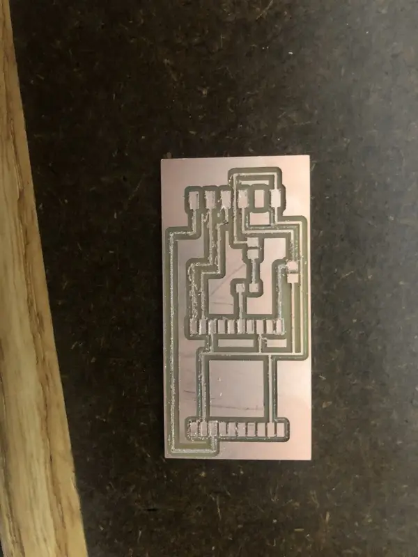
This is what the board looks like after milling:
The next step was to test the setup using an Arduino Uno and jumper wires to connect the pins.
However, I encountered a problem with my homemade breakout board. Despite its promising design, I accidentally ripped off the FTDI header, and was unable to desolder the GPS component even with extensive use of a heat gun. This was quite disappointing.
In the weeks that followed, I got busy with various projects and events, including “Make Big Things” week. Before I knew it, Thanksgiving break arrived and I had to head home. Wanting to continue working on my project, I decided to purchase the Ultimate GPS Module breakout board. In hindsight, I should have bought this board from the start. Using the second GPS module for a homemade breakout board would have required another challenging desoldering process.
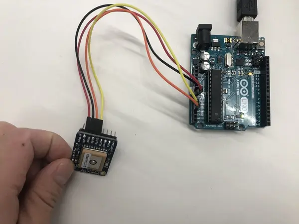
During Thanksgiving break, I connected the Ultimate GPS Module Breakout Board (designed by Lady Ada and her team) to an Arduino Uno to start programming it. This week was when I figured out the programming aspects, which I will discuss next.
The setup looked like this:
As for the troublesome GPS module component, Rob eventually helped me desolder it. I learned a valuable lesson: use solder wick to remove as much solder as possible before applying the heat gun to remove a component. This lesson proved to be very useful in the following weeks. Additionally, it turned out that the GPS module was actually undamaged and functioned properly on a test board I used later.
Programming
Programming a ATmega328P
To program the ATMega328P directly, it’s crucial to have the correct Arduino settings. You might assume you can use the Arduino/Genuino Uno board option since it also uses the ATMega328P. However, this setting requires an external 16MHz oscillator. If you prefer not to add this component to your board, you cannot use that Arduino setting.
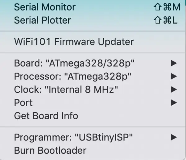
Instead, I installed specific ATMega328P boards from GitHub. These can be found here, with straightforward installation instructions provided in the README file. The default clock on the ATMega328P is 8MHz. Therefore, I set my settings to internal 8MHz, as shown in this image:
This was smooth sailing.
Programming on Mac
During the development of my final project, I discovered that programming boards on a Mac isn’t as difficult as I initially thought. You only need to install avrdude and an FTDI library. These can be easily found through a Google search, with FTDI instructions available here and avrdude instructions here. It’s quite convenient, although I encountered some issues with usbtiny programmers. Consequently, I ended up doing much of the programming on the GalliumOS Linux machine in the Harvard shop.
GPS stuff
The main objective of my project is to save GPS coordinates during activities like running or biking. To achieve this, I needed to determine where to store this information on the board. I discovered that GPS data can be efficiently stored in a format called NMEA, which is fascinating because each record is only 15 bytes, including time, elevation, latitude, longitude, and more. This compact format allows for extensive data storage in a small space.
Initially, I considered using a memory solution with megabytes of storage capacity. However, I realized it would be much simpler to use the onboard logging feature of the Ultimate GPS module. With 32KB of storage, it can hold about 2000 recordings, sufficient for many runs. The default recording interval is 10 seconds, which I changed to 5 seconds to obtain more detailed data.
I successfully implemented this using the Adafruit breakout board connected to an Arduino, with an interface for easy interaction. This process is documented here. Additionally, I created an interface to automate data dumping and erasing from the logger, also documented here.
While my final GPS-related code differs from what is documented, I will include all of my code at the end of this section.
Another requirement was converting the NMEA format to a more common GPS format, GPX. Unfortunately, there was no existing library to convert NMEA outputs to GPX, which is an XML-like format. This gave me the enjoyable task of writing one myself! Fortunately, there was a converter for NMEA to JSON, so I first converted NMEA to JSON, then JSON to GPX. All my code can be found on my GitHub here. I hope this library will be useful for others, and perhaps even for Adafruit.
OLED
I thought it would be dull for my project to simply record data without displaying anything. While I wasn’t initially sure what to show, I knew some form of visual output would be aesthetically pleasing and practically useful. I decided to buy an OLED screen, which we learned about during the Output Devices week in class. I chose the DIYMall 0.96” Blue and Yellow I2C OLED screen, available on Amazon for around $9 when I purchased it in November 2018. Fortunately, these prices have been decreasing over time.
Programming the OLED was relatively straightforward. Adafruit offers OLED screens of this format and provides numerous libraries that simplify the process. The main requirement is the Adafruit_SSD1306 library, available here. Additionally, the Adafruit GFX library, which can be installed directly from the Arduino IDE, is necessary. Using the example code ssd1306_128x64_i2c makes programming easy. One crucial detail is to change the display register from 0x3D to 0x3C; otherwise, it won’t work! I discovered this the hard way after a lot of trial and error and extensive Googling.
Another important point is that if you’re programming on a microcontroller with limited RAM, you might not be able to fully utilize the 128×64 screen because each pixel requires memory. For example, on the ATMega328P, which has 2K SRAM, it’s impossible to use both a 128×64 screen and SoftwareSerial due to RAM limitations. I resolved this by setting the SCREEN_HEIGHT to 32, which allowed enough RAM for Software Serial communication with the GPS module. This was a tricky bug that emerged when integrating the OLED and GPS module, both of which worked well individually, but the OLED failed to initialize when combined.
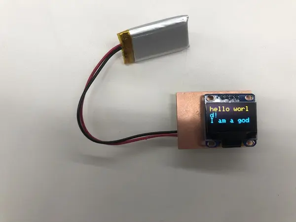
I was thrilled when I first got the OLED working:
Another point to note is that the example code provided is quite extensive. You don’t need all of it to perform basic tasks like displaying a string, which is likely the primary use case for most people.
Despite this, I highly recommend this component. It’s very user-friendly from a programming standpoint.
These were the main concerns I had while coding. Flash memory wasn’t a significant issue since the ATMega328P has 32KB, and I only used about 22KB. Here is my main Arduino file:
// Test code for Adafruit GPS modules using MTK3329/MTK3339 driver
//
// This code shows how to listen to the GPS module in an interrupt
// which allows the program to have more 'freedom' - just parse
// when a new NMEA sentence is available! Then access data when
// desired.
//
// Tested and works great with the Adafruit Ultimate GPS module
// using MTK33x9 chipset
//    ------> http://www.adafruit.com/products/746
// Pick one up today at the Adafruit electronics shop
// and help support open source hardware & software! -ada

#include <Adafruit_GPS.h>
#include <SPI.h>
#include <Wire.h>
#include <Adafruit_GFX.h>
#include <Adafruit_SSD1306.h>
#include <SoftwareSerial.h>

// Declarations for OLED
#define SCREEN_WIDTH 128 // OLED display width, in pixels
#define SCREEN_HEIGHT 32 // OLED display height, in pixels
#define OLED_RESET     4 // Reset pin # (or -1 if sharing Arduino reset pin)
Adafruit_SSD1306 display(SCREEN_WIDTH, SCREEN_HEIGHT, &Wire, OLED_RESET);

// If you're using a GPS module:
// Connect the GPS Power pin to 5V
// Connect the GPS Ground pin to ground
// If using software serial (sketch example default):
//   Connect the GPS TX (transmit) pin to Digital 3
//   Connect the GPS RX (receive) pin to Digital 2
// If using hardware serial (e.g. Arduino Mega):
//   Connect the GPS TX (transmit) pin to Arduino RX1, RX2 or RX3
//   Connect the GPS RX (receive) pin to matching TX1, TX2 or TX3

// If you're using the Adafruit GPS shield, change
// SoftwareSerial mySerial(3, 2); -> SoftwareSerial mySerial(8, 7);
// and make sure the switch is set to SoftSerial

// If using software serial, keep this line enabled
// (you can change the pin numbers to match your wiring):
SoftwareSerial mySerial(A2, A1);

// If using hardware serial (e.g. Arduino Mega), comment out the
// above SoftwareSerial line, and enable this line instead
// (you can change the Serial number to match your wiring):

//HardwareSerial mySerial = Serial1;


Adafruit_GPS GPS(&mySerial);


// Set GPSECHO to 'false' to turn off echoing the GPS data to the Serial console
// Set to 'true' if you want to debug and listen to the raw GPS sentences.
#define GPSECHO  true

// this keeps track of whether we're using the interrupt
// off by default!
boolean usingInterrupt = false;
void useInterrupt(boolean); // Func prototype keeps Arduino 0023 happy

int count = 0;

void setup()
{

  // connect at 115200 so we can read the GPS fast enough and echo without dropping chars
  // also spit it out
  Serial.begin(115200);
  Serial.println("Adafruit GPS library basic test!");

  // 9600 NMEA is the default baud rate for Adafruit MTK GPS's- some use 4800
  GPS.begin(9600);

  // uncomment this line to turn on RMC (recommended minimum) and GGA (fix data) including altitude
  GPS.sendCommand(PMTK_SET_NMEA_OUTPUT_RMCGGA);
  // uncomment this line to turn on only the "minimum recommended" data
  //GPS.sendCommand(PMTK_SET_NMEA_OUTPUT_RMCONLY);
  // For parsing data, we don't suggest using anything but either RMC only or RMC+GGA since
  // the parser doesn't care about other sentences at this time

  // Set the update rate
  GPS.sendCommand(PMTK_SET_NMEA_UPDATE_1HZ);   // 1 Hz update rate
  // For the parsing code to work nicely and have time to sort thru the data, and
  // print it out we don't suggest using anything higher than 1 Hz

  GPS.sendCommand("$PMTK187,1,5*38");

  if (GPS.LOCUS_StartLogger())
    Serial.println(" STARTED!");
  else
    Serial.println(" no response :(");

  // Request updates on antenna status, comment out to keep quiet
  GPS.sendCommand(PGCMD_ANTENNA);
  if(!display.begin(SSD1306_SWITCHCAPVCC, 0x3C)) { // Address 0x3C for 128x64
    Serial.println(F("SSD1306 allocation failed"));
    for(;;); // Don't proceed, loop forever
    display.display();
    delay(2000);
    display.clearDisplay();
  }

  // the nice thing about this code is you can have a timer0 interrupt go off
  // every 1 millisecond, and read data from the GPS for you. that makes the
  // loop code a heck of a lot easier!
  useInterrupt(true);

  delay(1000);
  // Ask for firmware version
  mySerial.println(PMTK_Q_RELEASE);
}


// Interrupt is called once a millisecond, looks for any new GPS data, and stores it
SIGNAL(TIMER0_COMPA_vect) {
  char c = GPS.read();
  // if you want to debug, this is a good time to do it!
#ifdef UDR0
  if (GPSECHO)
    if (c) UDR0 = c;
    // writing direct to UDR0 is much much faster than Serial.print
    // but only one character can be written at a time.
#endif
}

void useInterrupt(boolean v) {
  if (v) {
    // Timer0 is already used for millis() - we'll just interrupt somewhere
    // in the middle and call the "Compare A" function above
    OCR0A = 0xAF;
    TIMSK0 |= _BV(OCIE0A);
    usingInterrupt = true;
  } else {
    // do not call the interrupt function COMPA anymore
    TIMSK0 &= ~_BV(OCIE0A);
    usingInterrupt = false;
  }
}

uint32_t timer = millis();
void loop()                     // run over and over again
{
  // in case you are not using the interrupt above, you'll
  // need to 'hand query' the GPS, not suggested :(
  if (! usingInterrupt) {
    // read data from the GPS in the 'main loop'
    char c = GPS.read();
    // if you want to debug, this is a good time to do it!
    if (GPSECHO)
      if (c) Serial.print(c);
  }

  // if a sentence is received, we can check the checksum, parse it...
  if (GPS.newNMEAreceived()) {
    // a tricky thing here is if we print the NMEA sentence, or data
    // we end up not listening and catching other sentences!
    // so be very wary if using OUTPUT_ALLDATA and trytng to print out data
    //Serial.println(GPS.lastNMEA());   // this also sets the newNMEAreceived() flag to false

    if (!GPS.parse(GPS.lastNMEA()))   // this also sets the newNMEAreceived() flag to false
      return;  // we can fail to parse a sentence in which case we should just wait for another
  }

  // if millis() or timer wraps around, we'll just reset it
  if (timer > millis())  timer = millis();

  // approximately every 2 seconds or so, print out the current stats
  if (millis() - timer > 2000) {
    count++;
    timer = millis(); // reset the timer

    Serial.print("Fix: "); Serial.print((int)GPS.fix);
    Serial.print(" quality: "); Serial.println((int)GPS.fixquality);
    if (GPS.fix) {
      Serial.print("Speed (knots): ");Serial.println(GPS.speed);
      Serial.print("Satellites: "); Serial.println((int)GPS.satellites);
    }
      display.clearDisplay();
      display.setTextSize(2);      // Normal 1:1 pixel scale
      display.setTextColor(WHITE); // Draw white text
      display.setCursor(0, 0);     // Start at top-left corner
      display.cp437(true);         // Use full 256 char 'Code Page 437' font

    if (!GPS.fix){
      display.print("No signal :( ");
      display.print(count);
    } else {
      float speed = GPS.speed;
      display.print(knots_to_pacemin(speed));
      display.print(":");
      int secs = knots_to_pacesec(speed);
      if (secs < 10){
       display.print("0");
      }
      display.print(secs);
      display.println(" ");
      display.print(count);
    }
    display.display();
  }
}

int knots_to_pacemin(float speed) {
  return (int) (speed/1.15078*60);
}

int knots_to_pacesec(float speed) {
  return ((speed/1.15078*60) - (float) knots_to_pacemin(speed)) * 60;
}
Dumping data happened separately – can see my Interfaces week to see how I did that.
Electronics
Choices
I chose the ATMega328P microcontroller for its popularity and ample flash memory. Its widespread use means there is extensive documentation available, and testing can be easily done with an Arduino Uno, which also uses this microcontroller. I wanted to avoid concerns about memory limitations.
To keep the design compact, I opted to use as few components as possible, such as omitting external oscillators.
For power, I needed a battery and decided to use a 110mAh lithium-polymer battery available in the Harvard Lab. Initially, I considered using a larger battery, but it wasn’t suitable for the form factor, and I found that the board’s power consumption was manageable with the smaller battery.
Board Design
I spent over 24 hours designing my board to make it as compact as possible. My first step was creating a generic ATMega328P board, which was very useful for isolating errors by comparing them to this basic version.
The components needed were:
- ATMega328P
- 2x 10K resistors
- Switch
- 1x 1K resistor
- 2×3 header
- FTDI header
- LED
- JST 2-pin connector (for the battery, optional)
I kept my design very tight to conserve space, aiming to practice space-saving techniques for my final board.
Follow this link for complete project: Portable GPS Watch: Revolutionizing Fitness Tracking


