Summary of ARDUINO-CONTROLLED COIL WINDER
Pisces Printing redesigned their Arduino-controlled coil winder to be faster and more reliable. The updated build uses a linear rail and leadscrew driven by a stepper motor, an Arduino Nano with push buttons and a 16x2 LCD, faster steppers, an improved PCB with a buck converter, and a 3D-printed three-jaw chuck for holding bobbins.
Parts used in the Coil Winder:
- Linear rail
- Leadscrew
- Stepper motor (faster model)
- Arduino Nano
- Push buttons
- 16 x 2 LCD display
- PCB with buck converter power supply
- 3D-printed three-jaw lathe-style chuck
- Coil bobbin (workpiece)
Coil winders are a popular project because doing the deed manually can be an incredibly tedious and time consuming task. After building one such rig, [Pisces Printing] wanted to find even further time savings, and thus designed an improved, faster version.
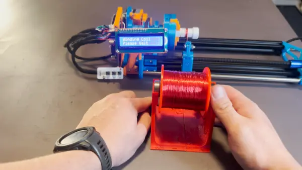
At it’s heart, it’s a straightforward design, using a linear rail and a leadscrew driven by a stepper motor. Control is via an Arduino Nano, with a few push buttons and a 16 x 2 LCD display for user feedback.
Often, completing a first build will reveal all manner of limitations and drawbacks of a design. In this case, the original winder was improved upon with faster stepper motors to cut the time it took to wind a coil. A redesigned PCB also specified a better buck converter power supply to avoid overheating issues of the initial design. A three-jaw lathe-style chuck was also 3D printed for the build to allow easy fixing of a coil bobbin.
Designing custom tools can be highly satisfying in and of itself, beyond the productivity gains they offer. Video after the break.
Source: ARDUINO-CONTROLLED COIL WINDER
- What is the core mechanical motion used in the coil winder?
The winder uses a linear rail and a leadscrew driven by a stepper motor for motion. - What microcontroller is used to control the coil winder?
The design uses an Arduino Nano for control. - How does the user interact with the coil winder?
Interaction is via a few push buttons and a 16 x 2 LCD display for feedback. - How was winding speed improved in the redesign?
Speed was improved by using faster stepper motors. - What change was made to address overheating in the original design?
The redesigned PCB specified a better buck converter power supply to avoid overheating issues. - How are bobbins secured during winding?
A three-jaw lathe-style chuck was 3D printed to hold the coil bobbin. - Is the project documented with video?
Yes, a video demonstrating the design is linked in the article.