Summary of Biomedical Device
Biomedical engineering project requires teams to design a prosthetic or wearable prototype using provided materials, incorporating sensors, Arduino control, machining (e.g., 3D printing), CAD drawings, circuit diagrams, cost estimates, Microsoft Project schedule, and an engineering notebook. Milestones and two Benchmarks enforce staged deliverables (PDI, CAD, sensors, machined parts, motor/sensor integration, and demos). Extra credit tasks are available. Devices must be autonomous, self-powered, contain no breadboards in the final unit, and meet specified functional tasks for prosthetics or wearables.
Parts used in the Biomedical Device Project:
- Arduino board
- Sensors (UV, temperature, heart rate, gas)
- Motors/servos
- Power source (battery)
- Wires and connectors
- 3D printing filament
- Mechanical frame/body materials (acrylic, wood, or plastics)
- Soldering supplies
- Display or touchscreen (optional for extra credit)
- Miscellaneous low-cost items (tape, fasteners)
Introduction and Overview
Biomedical engineering, a highly interdisciplinary field within STEM, offers opportunities for engineering and computer science students to engage in its endeavors. It involves the application of biology and engineering principles to create novel devices aimed at enhancing healthcare and medical options. Prominent examples of biomedical devices encompass artificial organs, prosthetics, wearables, and surgical robots.
The field of biomedical engineering has already made a significant impact by saving and enhancing numerous lives. Your objective is to contribute to this progress by developing one such device. Your group has been assigned the task of creating either a prosthetic or a wearable device that can significantly enhance the user’s quality of life. To be considered a functional prototype, the prosthetic or wearable you develop must fulfill certain fundamental requirements.
Example Projects
Specifications
Your team’s objective is to design a biomedical device utilizing the provided materials. Additionally, you are required to develop an Arduino program that will govern the device’s functions, sensors, and movements. It is necessary to present a cost estimate for the components used in the device. All modifications made to the original design must be thoroughly documented and explained. This includes technical design drawings, along with cost estimates. Any revisions made to the Arduino program must also be recorded and justified.
The biomedical device must demonstrate consistent and effective performance in a predetermined set of tasks. You can choose from the Device Choices list provided for the biomedical device options. Furthermore, the device must meet the following requirements:
1. Operate independently and possess its own power source.
2. Comprise a unified and self-contained structure without any loose or dangling components.
3. Capable of autonomously executing all designated tasks.
4. Control all outputs through sensor or electrical inputs.
5. Consult the BMD Sensors Guide for assistance in utilizing common BMD sensors.
6. Incorporate at least one machining technique.
7. Exclude the use of a breadboard in the final device.
8. Ensure complete autonomy of the device without any alterations or switches during the Benchmarking and Commissioning stages. Refer to the course syllabus for specific submission deadlines.
Device Choices
You are required to select one option for your project from the following two choices:
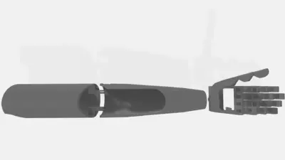
Option 1: Prosthetic Option
Develop an artificial limb, a wearable piece of technology designed to effectively replace a missing body part. The artificial limb must incorporate features that emulate a hand, a wrist, and an elbow. However, only two of these features need to be fully functional. To be considered functional, a feature must successfully complete the following tasks:
– The hand should be capable of grasping a shopping bag handle and lifting a 1-pound weight.
– The elbow must exhibit vertical movement of at least 90 degrees.
– The wrist should be capable of rotating at least 180 degrees.
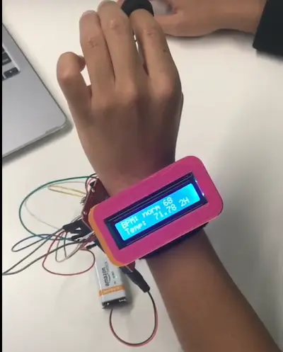
Option 2: Wearable Option
Create a wearable device, a technology worn on the human body that provides valuable health or fitness information to the user. This device must be capable of performing at least two of the following functions:
– Measure and display UV intensity data, providing information on safe exposure duration before it becomes harmful.
– Measure and display temperature data, indicating the safe exposure duration before it becomes harmful.
– Monitor and display heart rate, issuing warnings when irregularities are detected.
– Measure and display gas data in the surrounding area, issuing warnings if the air quality is hazardous.
– Display the current date and time.
For a comprehensive list of available materials accessible to all BMD groups, please refer to the provided “Available materials” resource.
Machining Methods
The following machining methods will be considered for Benchmarking, Commissioning, and Extra Credit. Currently, EG1004 offers 3D printing as the primary method, while other machining techniques are available through the MakerSpace. To utilize the MakerSpace machines, you are required to complete the MakerSpace Safety Orientation and sign up for a training session (training times can be viewed here). It’s important to note that some of these methods may require additional materials that may not be accessible to all groups.
1. 3D Printing (plastics):
This additive machining method is suitable for creating small and intricately designed 3D objects. While EG1004 provides access to basic 3D printing resources, the MakerSpace offers a wider range of filament types and build plate dimensions. Additional information can be found in the online MakerSpace 3D Printing Training (NYU Login is required).
2. Laser Cutting (wood or acrylic):
Laser cutting is a subtractive machining method ideal for precise cutting and engraving of 2D figures. It is particularly useful for efficient production of boxes. Further details can be found in the online MakerSpace Laser Cutting Training.
3. CNC Milling (wood, plastics, and soft metals):
CNC milling is a subtractive machining technique suitable for cutting and etching 2D or 3D shapes from various materials. The MakerSpace provides access to CNC milling machines. Comprehensive information is available in the online MakerSpace Othermill CNC Training.
4. Woodwork (hand and power saws available in the MakerSpace):
The MakerSpace offers a variety of power tools for woodworking purposes. These tools can be utilized for shaping and cutting wood. Detailed guidelines can be found in the online MakerSpace Power Tools Training.
Please refer to the appropriate training resources and comply with the necessary safety measures when utilizing these machining methods.
Microsoft Project
To effectively manage your project timeline, you are required to create a project schedule using Microsoft Project. To familiarize yourself with Microsoft Project, access the Microsoft Project Student Guide. The schedule should encompass all project-related tasks from the project’s commencement to its submission. Here is a guide on how to transfer a file. Ensure that your Microsoft Project schedule includes the following elements:
1. Minimum of 20 tasks (excluding Milestones): Incorporate a comprehensive list of tasks required for the project, excluding milestones.
2. Clearly indicated milestones: Clearly identify milestones within the project plan, assigning them a duration of zero days.
3. Assignment of responsible individuals: Each task should be assigned to the person responsible for its completion. Include the names of the resources associated with each task.
4. Inclusion of Gantt chart: Utilize the “Copy Picture” function to incorporate the project plan’s Gantt chart into your presentations. Avoid taking a screenshot.
5. Display of Gantt chart alongside task list: Present both the Gantt chart and the list of tasks, ensuring they fit on a single slide.
6. Progress line on the Gantt chart: Clearly depict a progress line on the Gantt chart to indicate the project’s progress.
7. Clear status indication during the presentation: Explicitly state whether the project is on-time, behind schedule, or ahead of schedule during the presentation.
For assistance in planning the project and scheduling costs, refer to the manual page titled “Planning Project Scheduling & Costs.”
By following these guidelines and utilizing Microsoft Project effectively, you can create a comprehensive project schedule that will aid in managing your project’s timeline.
Drawings
As part of the Milestone presentations and Benchmark assessments, you will need to produce a CAD model of your device. You have the flexibility to utilize any CAD software of your choice. Fusion 360 is recommended as it is both used and taught in EG1004 labs and other SLDPs. You can download Fusion 360 for free using your NYU email. While other CAD software such as SolidWorks, Inventor, and Rhino are allowed, EG1004 does not provide resources for obtaining or learning those programs.
Using your selected CAD software, you are required to create four drawings of the device: front, top, most detailed side, and isometric views. Each drawing should incorporate sensors and motors as part of the design.
It is essential to document each revision made to the design. All changes should be thoroughly presented during the Milestone presentations. This ensures that the evolution of the design is well-documented and can be effectively communicated to assessors.
Diagrams
As part of the Milestones, presentations, and Benchmark assessments, you will need to generate both a circuit diagram and a schematic diagram of your device. These diagrams provide visual representations of your circuit and its components.
A circuit diagram presents a realistic depiction of your circuit, illustrating the physical layout of the wires and how they are interconnected with the components. This diagram, represented as Figure 2, allows for a clear understanding of the physical connections within the circuit.
On the other hand, a schematic diagram focuses on the functional aspects and plans of your circuit, without concerning itself with the physical arrangement of the wires. This diagram, shown as Figure 3, provides an overview of the circuit’s logical structure and helps in comprehending the circuit’s functionality.
Both the circuit diagram and the schematic diagram are crucial in effectively communicating the design and operation of your device during the assessment process.
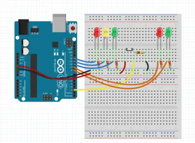
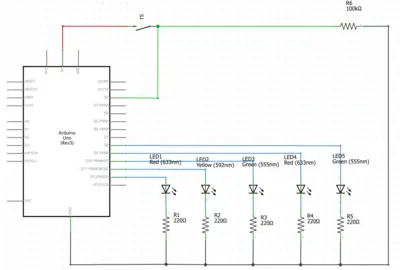
EG1004 suggests using Tinkercad and Fritzing as circuitry modeling software to fulfill the requirements of creating circuit and schematic diagrams. Tinkercad is a free, web-based software that offers a user-friendly interface for constructing circuit diagrams. It provides a wide range of common electrical components, making it particularly suitable for simpler circuit designs. On the other hand, Fritzing is a free circuitry software that offers an extensive library of electrical components, making it useful for constructing circuit and schematic diagrams, especially for projects involving more complex electrical components.
By referring to the Virtual Circuit Simulation Guide, you can access a comprehensive guide on using both Tinkercad and Fritzing. This guide will assist you in effectively utilizing these software tools to create accurate and detailed circuit and schematic diagrams for your project.
Cost Estimate
You are required to prepare a cost estimate that outlines the expenses for each component and the labor required for constructing the design. Use a clear and organized tabulation format in Microsoft Excel to present this cost information. Ensure that the materials used in the construction of your device are solely from EG1004’s inventory. If you wish to incorporate other parts, obtain prior permission from your faculty member. Your responsibility includes researching and estimating the cost of all components involved in the design’s construction. To aid in calculating the cost, you can refer to the Planning Project Scheduling & Costs page for assistance.
Your Microsoft Excel spreadsheet should adhere to the following specifications for the cost estimate:
1. Labor cost breakdown with hours and rates: Clearly outline the labor hours required for construction along with the corresponding rates.
2. Consolidate low-cost pieces: For items with lower costs like wires, tape, and servo motors, group them together for concise representation.
3. Itemize high-cost pieces: For components that are relatively expensive, such as Arduino boards, sensors, 3D printing filament, acrylic, and wood, list them separately to provide detailed information.
4. Clearly display the total cost: The total cost of the project should be visibly shown in the bottom right corner of the spreadsheet.
By presenting your cost estimate in an organized manner, you can effectively demonstrate the expenses involved in the construction of your design, including both materials and labor.
Engineering Notebook
During the course of your project, it is crucial to maintain a comprehensive record of all the work accomplished, along with future plans and objectives. This record is known as the Engineering Notebook. To fulfill the requirements for the Benchmark assessment, you will need to present your Engineering Notebook to the Open Lab TA conducting the assessment. For the Final Submission, the notebook should be in a Word Document format (DOC or DOCX) and must receive approval from an Open Lab TA.
You can refer to the Keeping an Engineering Notebook page for a guide on how to write and organize your notebook. This guide provides an overview of the expectations and the recommended frequency for logging entries in your notebook. By maintaining a well-structured Engineering Notebook, you can effectively document your progress, plans, and goals throughout the project’s duration, ensuring that you are well-prepared for both the Benchmark assessment and the Final Submission.
Extra Tasks
You have the opportunity to earn extra credit by completing up to two of the following tasks of your choice:
1. Accomplishing an additional Device Task.
2. Finishing Benchmark A, Benchmark B, or Submission ahead of schedule.
3. Integrating an extra sensor into the device.
– Each sensor should be implemented in a way that results in a measurable enhancement of the device’s performance.
4. Incorporating a display or touchscreen component into the design.
5. Developing a website or smartphone application that can interact with the device.
– The application must have the capability to interface with the device seamlessly.
6. Proposing your own task:
– If you have a unique idea for a task not listed above, you can present it to your Recitation TA and professor for approval before Benchmark B.
– Creativity and innovation are highly appreciated, and original designs may receive extra credit at the discretion of your Recitation professor.
– Specific point values for extra credit tasks can be found in the EG1004 Grading Policy.
By completing these additional tasks, you have the opportunity to showcase your skills, innovation, and dedication, potentially earning extra credit to enhance your overall project evaluation.
Milestones, Benchmarks, and Deliverables
During the course of your project, you will need to provide regular progress updates known as Milestones. These Milestones involve a set of deliverables, which can include written submissions, presentations, and demonstrations. These deliverables are essential to track and showcase the advancement of your project. Furthermore, you will also be expected to meet specific benchmarks assigned to your project. Submitting reports and deliverables aligned with these benchmarks contributes to the continuous progress and comprehensive development of your project.
To assist you with the 3D printing aspect of your project, you can refer to the Prototyping Guide, which contains valuable information on the requirements and guidelines for utilizing 3D printing resources effectively. This guide will aid in ensuring that your 3D printing tasks align with the project’s objectives and expectations.
Preliminary Design Investigation
The Preliminary Design Investigation (PDI) plays a crucial role in establishing the foundation for your project. It involves detailing your project concept, sources of inspiration, and set objectives.
The PDI should encompass the following components:
1. Cover Page
2. Project Overview
3. Goals & Objectives
4. Design & Approach
5. Cost Estimate
6. Project Schedule
7. Relevant Pictures
You can find an example PDI template at the provided link. The PDI is expected to be submitted by Benchmark A and can be reviewed and approved by any Open Lab TA. Ensure that all the items listed above are included in your submission. To access the PDI Rubric for evaluation criteria, use the link provided.
By thoroughly completing the PDI, you set the groundwork for a well-organized and informed project, providing a clear understanding of your project idea, objectives, and planned approach.
Milestone 1
For Milestone 1, your task is to present a condensed version of your Preliminary Design Investigation, avoiding mere replication of the report in presentation format. Focus on conveying the essential points in a concise and lucid manner, maintaining a similar section formatting as in the report. Emphasize outlining your project goals and demonstrating the feasibility of your project. This entails:
Milestone 1 Deliverables:
For Milestone 1, your presentation should include the following key elements:
1. Project Description: Provide a concise overview of your project, outlining its purpose and objectives.
2. Design Approach: Explain the methodology and approach you plan to adopt to achieve your project goals.
3. Mission Statement: Present a clear and definitive mission statement that encapsulates the core purpose and vision of your project.
4. Preliminary CAD Drawing of Device: Include an initial Computer-Aided Design (CAD) drawing of your device, giving a visual representation of its planned structure.
5. Cost Estimate: Provide an estimation of the project’s expenses, outlining the costs of components and labor.
6. Microsoft Project Schedule: Present a detailed schedule created using Microsoft Project, showcasing the timeline for various project tasks and milestones.
7. Progress Update: Offer a current status update on the project, highlighting any significant advancements made so far.
Important Note: At this stage, you are required to choose your project goal from the Device Choices list. Once you make this decision, you cannot change your device choice after the specified deadline.
Benchmark Assessment A
Benchmark assessments are crucial evaluations that assess the progress of your project. Benchmark Assessment A must be completed by the end of Model Shop Session II, and adhering to the deadline is important as there are penalties for late submission. For further details on grading policies, please refer to the EG1004 Grading Policy.
To successfully pass Benchmark A, your design must fulfill the following requirements:
1. Preliminary Design Investigation: Present a comprehensive Preliminary Design Investigation that outlines your project idea, goals, and approach.
2. Develop Initial CAD Model: Create your first design or concept for the hardware appearance of your device. Note that simple shapes and boxes will not be considered as an initial design.
3. One Working Sensor with Completed Wiring: Integrate one operational sensor into your design, with all wiring properly connected. Ensure that the Arduino code displays accurate data with appropriate units.
4. Submit .STL and .gcode Files of Team Logo: Provide both .STL and .gcode files of your team logo through the 3D Printing Submission portal on the EG website.
5. Prototyping and 3D Printing: Comply with the 3D printing requirements and guidelines outlined in the Prototyping Guide. You can find the protolab schedule in the same guide.
6. Updated Engineering Notebook: Keep your Engineering Notebook up to date with all the progress and activities related to the project.
By meeting these requirements, you can successfully pass Benchmark Assessment A and demonstrate substantial progress in your project’s development.
Milestone 2
Milestone 2 will be a project progress update. You must explain all changes and developments made thus far, particularly in regards to Benchmark A. Include whether or not you were able to complete your Benchmark A requirements, and if not, explain why. Also, highlight any changes you plan on making to your design or project, in general. Your Milestone 2 presentation must include:
Milestone 2 Deliverables:
- Project description
- Design changes since Milestone 1
- Design approach
- Mission statement
- CAD drawings: top, front, most detailed side, isometric
- Circuit diagram
- Flowchart of code
- Cost estimate (previous and current). What changes were made?
- Microsoft Project schedule (previous and current). What changes were made?
- Click here to access the guide on how to transfer a file
- Progress update: current state of the project (time, budget, etc.)
Benchmark Assessment B
Benchmark Assessment B is a crucial evaluation that must be completed by the end of Model Shop Session III. Timely completion is essential, as there are penalties for late submission, as outlined in the EG1004 Grading Policy.
To successfully pass Benchmark Assessment B, you are required to fulfill the following tasks:
1. Updated CAD Model: Showcase the modifications between your initial design and the new design. Provide clear visuals and explanations.
2. Machining Method Utilization: Utilize one of the accepted Machining Methods to manufacture the frame or body of your device. While the device does not need to be fully assembled, the individual pieces must be manufactured. For instance, you should laser cut all the individual pieces but not yet glue them together, or 3D print a claw and arm for your prosthetic without attaching them. Ensure you can explain how these pieces will be assembled and function.
3. Receive Soldering Training from EG: In-person students should receive training at Open Lab, while remote students should complete the MakerSpace Soldering Training and demonstrate their understanding through a completed quiz with a score of at least 80%.
4. Prosthetic Only: Control at least one motor using sensors, with the motors mimicking how they will function in the device (same direction, speed, angle, etc.). You should be able to explain how these motors will work to accomplish the required device tasks.
5. Wearable Only: Ensure that the device can complete at least one of the required tasks, and that data/warnings are not solely displayed on the Serial Monitor.
6. Approved .STL and .gcode Files of the Team Logo: Submit approved .STL and .gcode files of your team logo through the 3D Printing Submission portal on the EG website.
Incorporate these tasks into your project to successfully pass Benchmark Assessment B. Remember to update your Engineering Notebook to reflect the progress and activities related to your project. The Prototyping Guide contains essential information on 3D printing requirements and guidelines, and you can find the protolab schedule there as well.
- What are the two project choices?
Design either a prosthetic (hand, wrist, elbow; two features functional) or a wearable that performs at least two listed monitoring/display functions. - How must the device operate?
The device must operate independently with its own power source, be self-contained, and autonomously execute all designated tasks via sensor or electrical inputs. - Can a breadboard be used in the final device?
No, a breadboard cannot be used in the final device. - What machining methods are accepted?
Accepted methods include 3D printing, laser cutting, CNC milling, and woodwork using MakerSpace resources. - What must be included in the CAD drawings?
Four drawings: front, top, most detailed side, and isometric, showing sensors and motors. - What are Benchmark A requirements?
Submit PDI, initial CAD model (not simple boxes), one working sensor with wiring and Arduino code displaying units, team logo .STL and .gcode, and updated engineering notebook. - What additional tasks can earn extra credit?
Extra credit options include an extra device task, early completion, adding an extra sensor, including a display, creating an app or website, or proposing an approved custom task. - What must the cost estimate include?
The cost estimate must list component costs and labor (hours and rates), consolidate low-cost items, itemize high-cost pieces, and show total cost in the bottom right of the spreadsheet. - What does Benchmark B require for prosthetic projects?
Use a machining method to manufacture parts, receive soldering training, and control at least one motor with sensors mimicking final function. - How should circuit documentation be produced?
Produce both a circuit diagram (physical layout) and a schematic diagram (functional plan), using tools like Tinkercad or Fritzing.