Summary of Arduino Binary Clock (hours, minutes and seconds)
This article details a DIY Arduino binary clock project that displays hours, minutes, and seconds using 16 LEDs. The creator assembled the system with significant effort, utilizing an Arduino Uno, an RTC DS1307 module for timekeeping, two 74HC595 shift registers to manage the LED outputs, and standard prototyping components like breadboards and resistors. The provided C++ code drives the hardware, converting real-time data into binary patterns to illuminate specific LEDs representing the current time.
Parts used in the Arduino Binary Clock:
- Arduino Uno
- RTC DS1307
- 2 Shift Registers 74HC595
- 16 leds
- 16 330 ohm resistors
- Breadboards
- Jumpers
Hello everyone; I was looking for this project for a long time. Finally I it it together with a lot of effort. For this project you will need:
2- RTC DS1307 (like $2 from EBay)
3- 2 Shift Registers 74HC595 (like $1 eachh from Ebay)
4- 16 leds
5- 16 330 hom resistors
6- Breadboards
7- jumpers
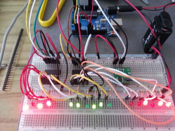
The clock will display the hours using the first 4 leds, then the minutes using the next 6 leds and finally the seconds using the las 6 leds.
There is a better explanation from the original project here (as well as other cool projects): http://www.multiwingspan.co.uk/arduino.php?page=bclock
Step 1: The schematics
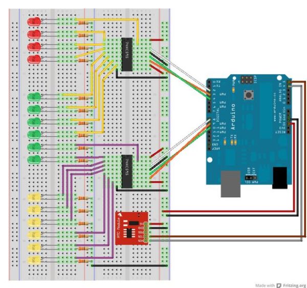
Here is the design; mounted in two full breadboards! (Make sure you’ve got all the connections right, fail to to so will give you a few days of headache; it happened to me!)
Step 2: The code (from http://www.multiwingspan.co.uk by M Atkinson)
//orignal code made by M Atkinson, please check his website http://www.multiwingspan.co.uk
//few minor modifications made by [email protected]
#include <Wire.h>
#include “RTClib.h”
RTC_DS1307 RTC;
int datapin = 2;
int clockpin = 3;
int latchpin = 4;
int datapin2 = 8;
int clockpin2 = 9;
int latchpin2= 10;
void setup()
{
Serial.begin(57600);
Wire.begin();
RTC.begin();
if (! RTC.isrunning()) {
Serial.println(“RTC is NOT running!”);
// following line sets the RTC to the date & time this sketch was compiled
//RTC.adjust(DateTime(__DATE__, __TIME__));
}
pinMode(datapin, OUTPUT);
pinMode(clockpin, OUTPUT);
pinMode(latchpin, OUTPUT);
pinMode(datapin2, OUTPUT);
pinMode(clockpin2, OUTPUT);
pinMode(latchpin2, OUTPUT);
}
void loop()
{
DateTime now = RTC.now();
// All used for checking the time of the clock
// This section can be removed when everything is working
Serial.print(now.hour(), DEC);
Serial.print(‘:’);
Serial.print(now.minute(), DEC);
Serial.print(‘:’);
Serial.print(now.second(), DEC);
Serial.println();
// End of section that can be removed
int mins = now.minute();
int secs = now.second();
int hr = now.hour();
// convert to 12 hour time
if (hr>12)
{
hr = hr-12;
}
// variables to describe pattern of on lights
byte data1 = 0;
byte data2 = 0;
// encode the time
// hr = 1st four bits controlled by the first shift register
for (int i =0;i<4;i++)
{
if (bitRead(hr,i)==1)
{
bitWrite(data1,3-i,1);
}
}
// mins on the first shift register (last 4 leds)
for (int i =2;i<6;i++)
{
if (bitRead(mins,i)==1)
{
bitWrite(data1,9-i,1);
}
}
// mins on the second shift register (first 2 leds)
for (int i =0;i<2;i++)
{
if (bitRead(mins,i)==1)
{
bitWrite(data2,1-i,1);
}
}
// seconds, controlled by the second shift register (all 6 leds)
for (int i =2;i<8;i++)
{
if (bitRead(secs,i-2)==1)
{
bitWrite(data2,9-i,1);
}
}
// output the information
writeByte(data1,1);
writeByte(data2,2);
// a pause every one second for the serial monitor output
delay(1000);
}
void writeByte(byte data, byte set)
{
int d,c,l;
if (set==1)
{
d = 2;
c = 3;
l = 4;
}
else if (set==2)
{
d = 8;
c = 9;
l = 10;
}
shiftOut(d, c, MSBFIRST, data);
// toggle the latch pin so that the data appears as an output
digitalWrite(l, HIGH);
digitalWrite(l, LOW);
}
For more detail: Arduino Binary Clock (hours, minutes and seconds)
- How is the time displayed on the clock?
The clock displays hours using the first 4 LEDs, minutes using the next 6 LEDs, and seconds using the last 6 LEDs. - Where can I purchase the major components?
Arduino Uno can be bought from Radio Shack, while the RTC DS1307 and shift registers are available on eBay. - What is the best way to ensure correct connections?
You must mount the design on two full breadboards and verify all connections to avoid headaches caused by errors. - Does the code include time conversion logic?
Yes, the code converts the hour to 12-hour format if the value is greater than 12. - Can I remove the serial monitor section of the code?
Yes, the section checking the time via Serial print can be removed once the clock is working correctly. - How does the code handle the shift register output?
The writeByte function toggles the latch pin HIGH then LOW after sending data to make it appear as an output. - What libraries are required for the code?
The code requires the Wire.h library and the RTClib.h library. - Is there an external resource for more details?
Yes, the original project explanation is available at http://www.multiwingspan.co.uk/arduino.php?page=bclock.