Summary of Arduino Skateboard Speedometer
This Instructable shows how to build an Arduino-based speedometer/tachometer for a man-powered vehicle (skateboard), using a magnet mounted in the wheel, a magnetic relay switch to count revolutions, and an LCD to display speed. It covers embedding the magnet, wiring the electronics with power, resistors and a potentiometer, securing connections, mounting the LCD, and adapting the conversion factor in code to compute MPH from RPM.
Parts used in the Arduino Skateboard Speedometer:
- A man-powered vehicle (skateboard)
- Arduino
- Plastic Arduino protective box
- Small magnet (approx 1/4 inch diameter, 0.2 inch tall)
- Magnetic relay switch
- 9V battery and adapter for Arduino power plug
- Small LCD screen (16 x 2 character display)
- 10K resistor
- 47 Ohm resistor
- Wires
- Soldering iron and solder
- Adhesive (Gorilla glue, super glue, or similar)
- 10K potentiometer
Using an Arduino, it is easy to make a speedometer/tachometer for virtually any man-powered vehicle. I made one for my skateboard that used a small magnet to count revolutions and utilized an LCD display screen. This Instructable will show you how you can do the same step by step.
You will need a few things before we get started.
1) A man-powered vehicle (I will be using a skateboard)
2) An Arduino
3) A plastic Arduino protective box (pictured)
4) A small magnet (mine is 1/4 inch in diameter and about 0.2 inches tall)
5) A magnetic relay switch
6) A 9V battery and an adapter that connects this battery to the Arduino plug (pictured above plugged into an Arduino)
7) A small LCD screen (16 x 2 character display)
8) 10K and 47 Ohm resistors
9) Wires
10) A soldering iron and solder
11) Gorilla glue, super glue, crazy glue, or some adhesive of the sort
12) 10K Potentiometer
Step 1: Putting the Magnet on the Wheel
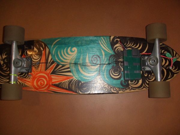
The first thing I did was embed the small magnet in my rubber skateboard wheel. I drilled a small hole (1/4″ diameter to fit the magnet snugly) on the inside of one of my back wheels toward the edge of the wheel. I then dropped some gorilla glue in this hole and fit the magnet in it so about half of the magnet’s height was imbedded in the wheel and half was sticking out of the wheel. Later this magnet will allow the magnetic relay switch to count the wheel’s revolutions when the relay switch is near the spinning magnet.
Step 2: The Electronics
The next step is to get all the electronics functioning. The circuit diagram can be seen here. The red connections indicate attachment to the Arduino’s +5V pin and the green connections are to the Arduino’s ground pin. You will want to solder (and probably also heat shrink) your connection points to ensure that the circuit doesn’t short itself out. This will also ensure that the connections (and thus speedometer) don’t fail while it is being used. You may want to wire everything up through a small piece of board separate from the Arduino. You can wire the pot, ground and +5V components to this board to minimize the connections into the actual Arduino pins. This will keep your electronics more organized and easier to work with. It is also important to consider where you will be mounting the LCD before you wire it all up. Depending on where you choose to mount your display, it may be necessary to take steps to ensure this connection is possible once the LCD is wired up. For example, since I mounted the LCD in my board and had the wiring go through a small hole I had to put the LCD in place and run the wiring through the hole to the LCD before I connected everything.
Step 3: The Arduino Code
With the electronics all wired up and secured, the next step is to code the Arduino. There are tons of codes out there for Arduino tachometers, so it shouldn’t be hard to find. The code I used for my speedometer/tachometer is attached.

One thing to note is the line that says “Serial.print(rpm*0.0080622311).” This line will be different for everyone. This line of code calculates the speed in MPH from the RPM value the relay and Arduino read. To do this you take:
2) An Arduino
3) A plastic Arduino protective box (pictured)
4) A small magnet (mine is 1/4 inch in diameter and about 0.2 inches tall)
5) A magnetic relay switch
6) A 9V battery and an adapter that connects this battery to the Arduino plug (pictured above plugged into an Arduino)
7) A small LCD screen (16 x 2 character display)
8) 10K and 47 Ohm resistors
9) Wires
10) A soldering iron and solder
11) Gorilla glue, super glue, crazy glue, or some adhesive of the sort
12) 10K Potentiometer
For more detail: Arduino Skateboard Speedometer
- How is the magnet mounted on the wheel?
Drill a 1/4 inch hole toward the inside edge of the wheel, drop glue in, and press the magnet so about half its height is embedded and half protrudes. - What sensor counts wheel revolutions?
A magnetic relay switch detects the passing magnet and allows the Arduino to count revolutions. - What display is used for speed output?
A 16 x 2 character LCD screen is used to display speed and RPM. - How is the circuit powered?
With a 9V battery connected to the Arduino via a battery adapter plug. - What should I do to prevent shorts and loose connections?
Solder connections and use heat shrink; optionally wire through a small board to organize connections. - Do I need to consider LCD mounting before wiring?
Yes; mount the LCD or run its wiring through mounting holes before final connections to ensure proper fit. - How is speed in MPH calculated in the code?
The code multiplies rpm by a conversion factor (example given: rpm * 0.0080622311) which must be adjusted for your wheel size. - Are resistor and potentiometer values specified?
Yes; the project uses a 10K resistor, a 47 Ohm resistor, and a 10K potentiometer.