
Summary of An Alarm Clock (but It Is Harder to Turn Off)
This project is a 3D-printed Arduino-based alarm clock that requires shaking to snooze and solving a randomly generated math question to fully turn off the alarm. It includes timekeeping, alarm setting, an I2C LCD and 7-segment display, pushbutton inputs multiplexed via resistor ladder to one analog pin, accelerometer-based motion detection, and a buzzer. The build used breadboard prototyping, Fusion 360 enclosure design, soldering, and Arduino code organizing multiple subroutines for time, alarm, snooze, question generation, and answer verification.
Parts used in the Alarm Clock (but It Is Harder to Turn Off):
- 3D Printer & filament
- Arduino Nano
- I2C LCD display
- 4 Pushbuttons
- 7-Segment Display
- LIS331 Adafruit Accelerometer
- DS3231 Real-Time-Clock
- Piezo Buzzer
- 3x 4.7k resistors
- 4x 1k resistors
The inspiration for this project was the dreadfully painful waking up process in the morning. And now that school is starting back up I had to get off of the summer schedule where you could get away with not waking up at the crack of dawn. Often times I’d find myself snoozing my alarm clock over and over in a haze before even realizing it. The intent of this design is to make sure you’re somewhat awake before the noise goes away and you can go back to sleep.
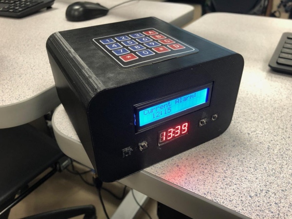
The concept behind this project is an alarm clock that needs to be joggled or shaken to snooze – then a randomly generated math question must be answered to kill the alarm for good. Obviously it must also function as a clock that can keep time and have some way to set an Alarm.
Supplies
3D Printer & filament
Arduino Nano
I2C LCD display
4 Pushbuttons
7-Segment Display
LIS331 Adafruit Accelerometer
DS3231 Real-Time-Clock
Piezo Buzzer
3x 4.7k resistors
4x 1k resistors
Step 1: Design Ideas
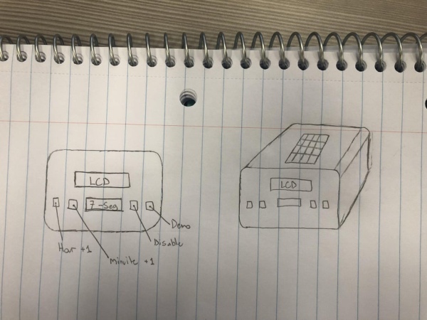
I knew I didn’t really want a boxy design for the alarm clock. I also realized a super curved design wouldn’t allow for the room needed for all of the components. I settled on a rounded design that I thought would look mildly appealing.
Step 2: Fusion 360 CAD Model
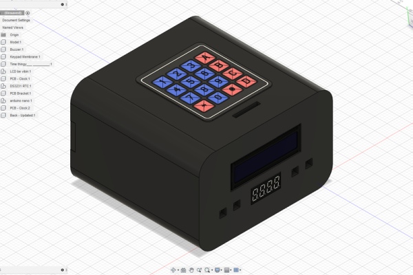
With a general design in hand all that was left was to transfer it into fusion 360. I had to measure the electrical components to get the correct spacing for the holes. The back plate I designed just utilized little stopping tabs and a friction mount – it ended up working very well.
Step 3: Electronics Prototyping
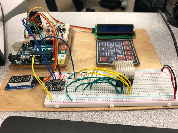
Before I threw all of the components into a box all soldered together I made sure everything worked and was programmed while on a breadboard. This let me easily debug as I was working.
Step 4: Coding
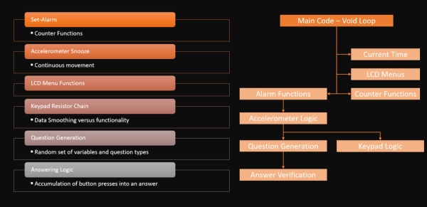
I’ll attach the source code here. I have a general diagram of how the code interacts with certain subroutines. There are some things that need to run all the time, or at least most of the time. Things like setting the alarm set time, display, or the actual time. Now when the alarm actually goes of it sets of a chain of events, first the accelerometer for the snooze detection then random questions are generated & displayed and finally the answer verification starts running to determine if the answer is correct.
In this project I ran the keypad connections through a series of resistors and connected the inputs to the ends of each one so I could read a unique analog output for each button press. This allowed all of the keypad wires to be reduced to a single one.
This was one of my first coding projects and it was a lot of fun.
Note: to use the Arduino sketch all the files need to be dropped into a folder called ‘Main7’ and as the name implies that’s the main sketch that includes the setup and void loop.
Step 5: Construction
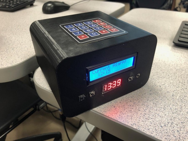
The big hurtle with the construction is soldering everything together, the 3D prints are pretty much good to go except some hot glue and a few screws. The soldering isn’t too bad but I certainly made some rookie mistakes while soldering which caused the death of an accelerometer and the re-soldering of many wires that fell apart (solid core wires work a lot better).
Step 6: Demo
Source: An Alarm Clock (but It Is Harder to Turn Off)
- How does the snooze function work?
Snooze requires joggling or shaking the clock detected by the accelerometer before the alarm can be silenced temporarily. - How is the alarm finally turned off?
The alarm is turned off by answering a randomly generated math question correctly. - Can the clock keep accurate time?
Yes; the project uses a DS3231 real-time clock for timekeeping. - How are multiple pushbuttons connected to the Arduino?
Pushbuttons are read via a resistor ladder producing unique analog voltages so multiple buttons use a single analog input. - Was prototyping done before final assembly?
Yes; all components and code were tested and debugged on a breadboard before final soldering and enclosure assembly. - What display types are used in the project?
The project uses an I2C LCD display and a 7-segment display. - Is the enclosure custom designed?
Yes; a rounded enclosure was modeled in Fusion 360 with measured mounting features and a friction-fit back plate. - Are the Arduino sketch files provided?
Yes; the source code is attached and must be placed in a folder named Main7 for the main sketch with setup and loop.
