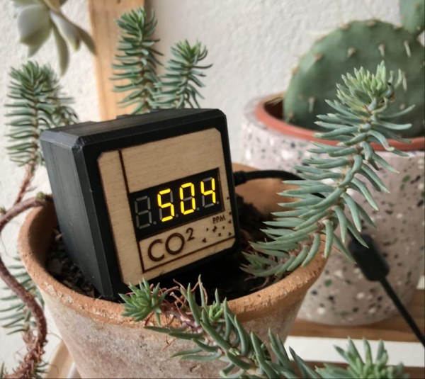
As its name suggests, the CO2 Display project is a small CO2 gas sensor to be plugged into USB to easily track indoor and outdoor pollution.
The CO2 level is displayed live, but it is possible with the small application provided in the documentation to generate capture samples in image (in png format) and in list file (in csv format). To better interpret the data here is a table of the PPM scale (unit of measurement of CO2).
—-
Comme son nom l’indique, le projet Afficheur CO2 est un petit capteur
de gaz CO2 à brancher sur USB pour traquer facilement la pollution intérieur comme extérieur.
L’affichage du taux de CO2 se fait en direct, mais il est possible avec la petite application fournit dans la documentation de générer des échantillons de capture en image (au format png) et en fichier liste (au format csv).
Pour mieux interpréter la donnée voici un tableau d’échelle des PPM (unité de mesure du CO2)
Step 1: Equipment List
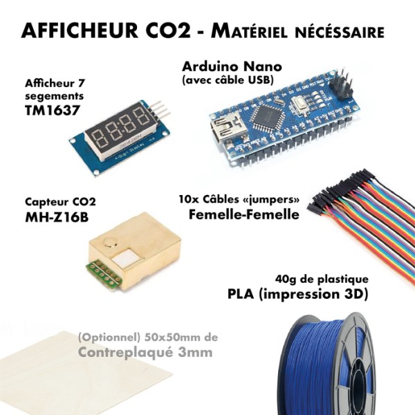
To make this sensor we opted for the MZ-H19B sensor, relatively inexpensive, compact, reliable in its measurements and with a lifespan of more than 5 years, it seemed to us that this sensor was the most suitable for our use as a portable sensor.
To mount the sensor you will need to purchase the following list of equipment:
– MH-Z19B CO2 sensor
– Arduino Nano microcontroller (with USB cable)
– 7-segment display TM1637
– 10 Prototyping cables female <> female jumpers.
– 40g of PLA for 3D printer
– (Optional) 50x50mm of 3mm plywood.
——-
Pour faire ce capteur nous avons opté pour le capteur MZ-H19B,
relativement peu cher, compact, fiable dans ses mesures et avec une durée de vie supérieure à 5ans il nous semblait que ce capteur était le plus indiqué pour notre usage de capteur portable.
Pour monter le capteur il vous faudra acheter la liste de matériel suivante :
– Capteur de CO2 MH-Z19B
– Microcontrôleur Arduino Nano (avec câble USB)
– Afficheur 7 segments TM1637
– 10 Câbles de prototypage « jumpers » femelle<>femelle.
– 40g de PLA pour imprimante 3D
– (En option) 50x50mm de bois contreplaqué 3mm.
Step 2: Build the Sensor Shell 1/2
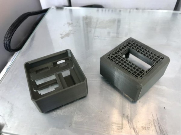
To mount the sensor, you will also need to download and print the 2 elements of the housing shell. There are 3 files: 1 for the facade (FacadeBois.pdf / FacadeBois.svg) and 2 for the rear (BoitierFond.stl and BoitierFaceBois.stl). If you do not have a laser cutter you can only download and make BoitierFace.stl.
To print we advise you to use a 0.4mm nozzle for a 0.1mm layer. Depending on your printer, you can expect to print part of the case in 3h15.
If you have printed BoitierFaceBois.stl, do not forget, once the printing is finished, to remove the supports necessary to print the object (see the photo).
—
Pour monter le capteur, il vous faudra également télécharger puis
imprimer les 2 éléments de la coque du boîtier. Il existe 3 fichiers une 1 pour la façade (FacadeBois.pdf / FacadeBois.svg) et 2 pour l’arrière (BoitierFond.stl et BoitierFaceBois.stl). Si vous n’avez pas de découpeuse laser vous ne pourrez que télécharger et réaliser BoitierFace.stl.
Pour imprimer nous vous conseillons d’utiliser une buse 0.4mm pour une couche de 0.1mm. En fonction de votre imprimante vous pouvez espérer imprimer une partie de boîtier en 3h15.
Si vous avez imprimez BoitierFaceBois.stl, n’oubliez pas, une fois l’impression terminée de retirer les supports nécessaire à l’impression de l’objet (voir sur la photo).
Step 3: Build the Sensor Shell 2/2 (option)
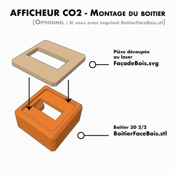
As an option, if you have printed BoitierFaceBois.stl you can cut the small front panel of the sensor out of 3mm thick wood and then assemble the two elements (see photo).
—
En option, si vous avez imprimé BoitierFaceBois.stl vous pouvez découper
la petite façade du capteur dans du bois de 3mm d’épaisseur pour ensuite assembler les deux éléments (voir la photo).
Step 4: Assemble the Electronics to the Shell
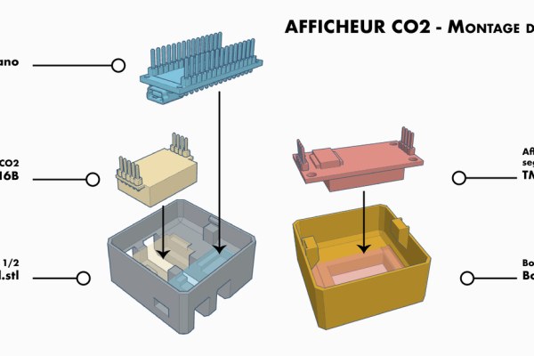
Now that you have all the elements in hand, you will be able to assemble the box with its sensors. To do so, follow the sketches and explanatory photos.
—-
Maintenant que vous avez tout les éléments en main vous allez pouvoir
assembler le boîtier avec ses capteurs. Pour se faire suivez les croquis et photos explicatifs.
Step 5: Manufacturing “Y”
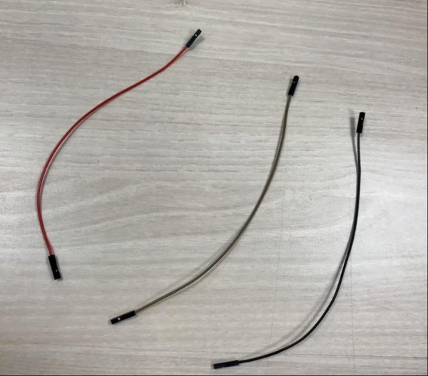
Be careful before you start wiring! Since the arduino only has a + 5v output, you are going to need to make Y cables that will power both components with a single 5v pin. To do this, provide yourself with 3 female-female jumpers to achieve 2 “Y” and follow the photos.
Once the Y’s are formed, make a spot weld to secure the wires. Then, to finish, provide yourself with a roll of chatterton to insulate the welds (beware of short circuits, which in such a small space will be inevitable)
—
Attention, avant de commencer à câbler ! Étant donné que la arduino
n’a qu’une sortie +5v, vous allez devoir fabriquer des câbles Y qui vont permettre d’alimenter les deux composants avec une seule pin 5v. Pour cela munissez vous de 3 jumpers femelle-femelle pour réaliser 2 “Y” et suivez les photos.
Une fois les Y formés, faites un point de soudure pour fixer les fils. Puis, pour finir, munissez-vous d’un rouleau de chatterton pour isoler les soudures (attention aux court-circuits, qui dans un espace aussi réduit seront inévitable)
Step 6: Wire the Object
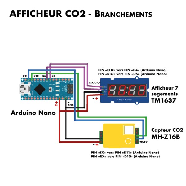
Now that you have your Y (s) and before closing the final box, you will need to connect the whole system with the rest of your female-female jumpers cables. To complete this step, follow the plan.
Pin D10 (arduino)> Pin TX (CO2 sensor)
Pin D11 (arduino)> Pin RX (CO2 sensor)
Pin D4 (arduino)> Pin CLK (7 seg display)
Pin D5 (arduino)> Pin DIO (7 seg display)
Pin 5v (arduino)> Pin V + (CO2 sensor), Pin Vcc (7 seg display)
Pin GND (arduino)> Pin V- (CO2 sensor), Pin Gnd (7 seg display)
—-
Maintenant que vous avez votre ou vos Y et avant de refermer le
boîtier finalisé, il vous faudra brancher tout le système avec le reste de vos câbles jumpers femelle-femelle. Pour réaliser cette étape, suiviez le plan.
Pin D10 (arduino) > Pin TX (capteur CO2)
Pin D11 (arduino) > Pin RX (capteur CO2)
Pin D4 (arduino) > Pin CLK (afficheur 7 seg)
Pin D5 (arduino) > Pin DIO (afficheur 7 seg)
Pin 5v (arduino) > Pin V+ (capteur CO2), Pin Vcc (afficheur 7 seg)
Pin GND (arduino) > Pin V- (capteur CO2), Pin Gnd (afficheur 7 seg)
Step 7: Close the Shell
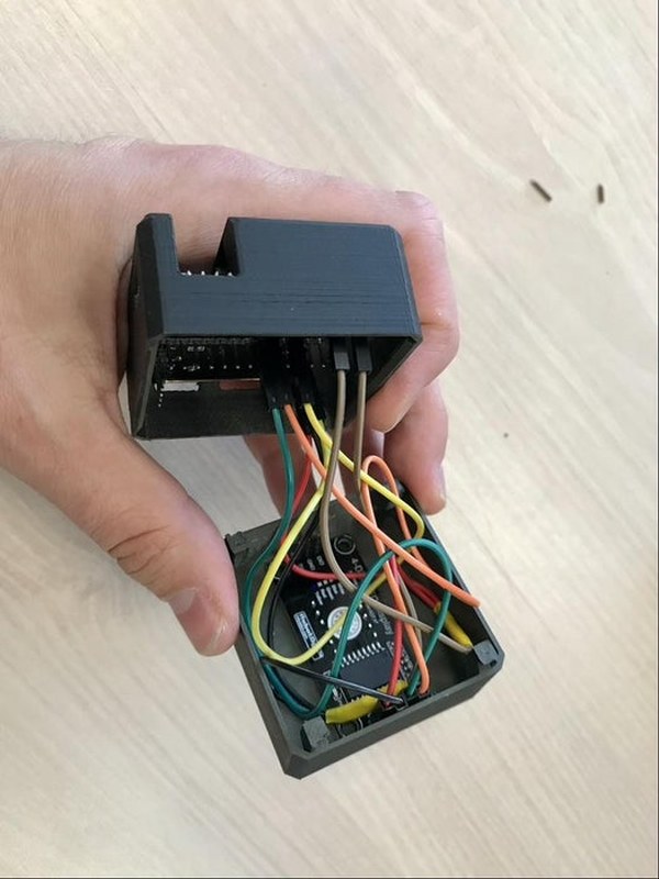
… paying careful attention to the cables.
—
… en faisant bien attention aux câbles.
Step 8: Upload the Arduino Code !
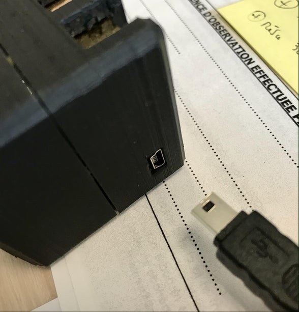
Now that the connection is functional, and that you have closed the box, connect the sensor to your computer.
Copy the code provided in the documentation then, Using the Arduino software, upload it to the Arduino Nano.
Once uploaded, the sensor should function properly and display the CO2 level live on the display.
—-
Maintenant que le branchement est fonctionnel, et que vous avez fermé le boitier, branchez le capteur sur votre ordinateur.
Copiez le code mis à disposition dans la documentation puis, Avec le logiciel Arduino, téléversez le dans la Arduino Nano.
Une fois televersé, le capteur devrait fonctionner correctement et afficher le taux de CO2 en direct sur l’afficheur.
Step 9: [Work in Progress] Save the Data!
If you want to go further and store the displayed values live, we suggest you use the small processing application [To finish]. This application will automatically save a capture log (as a csv list file and a graphic in png format).
To make the application work correctly, follow these steps:
1- launch the application on a computer
2- connect the sensor to this computer
3- let the sensor connect for the desired time
4- to end the sampling, unplug the sensor, the application will generate the capture files automatically. These are stored by default in the same folder where the application is located.
—
Si vous voulez allez plus
loin et stocker les valeurs afficher en direct, nous vous proposons d’utiliser la petite application processing [A finir]. Cette application enregistra automatiquement un journal de capture (sous forme de fichier liste csv et de graphique au format png).
Pour faire fonctionner correctement l’application, suiviez ces étapes :
1- lancez l’application sur un ordinateur
2- branchez le capteur sur cet ordinateur
3- laissez le capteur branchez le temps voulu
4- pour mettre fin à l’échantillonnage, débranchez le capteur, l’application générera les fichiers de captures automatiquement. Ces derniers sont stockés par défaut dans le même dossier où est situé l’application.
Source: CO2 Display