Summary of Ez Arduino 12 DOF Quadruped Robot – Robot Dog Lassie
This guide shows how to build a low-cost 3D-printed 12-DOF quadruped robot (Robot Dog Lassie) controlled by a HuaDuino (Arduino Nano-compatible) and a smartphone via Bluetooth. It covers 3D printing settings, required electronics and servos, Bluetooth module configuration, firmware upload, wiring pinouts, and assembly steps with video references. The design uses common components and provides apps for BLE and classic SPP control.
Parts used in the Robot Dog Lassie:
- 3D-printed PLA parts (STL models)
- HuaDuino board (Arduino Nano compatible)
- 3.7V 18650 lithium ion battery with XH2.54 connector
- 12 x Tower Pro MG90s or compatible clone servos
- 5V buzzer
- Bluetooth module (HC-06, HC-05, SPP-CA classic or BT-05 CC2540/HM-10/CC41-A BLE)
- Female-female DuPont wires (or equivalent)
- M2x6 and M2x10 tapping screws
- M3x6, M3x14, M3x20 flat head screws and M3 nuts
- Smartphone with compatible control app (goBLE, virtual-Gamepad-BLE, virtual-gamepad-SPP)
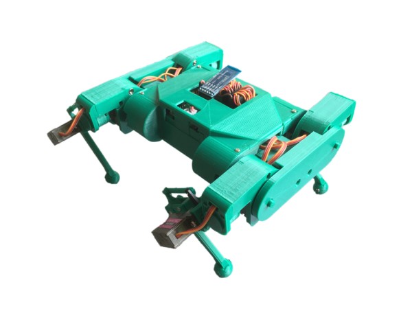
Since Boston Dynamics presented their quadruped robot named Spot, everybody wants their own robot dog. There have been several efforts to create a robot with the same features. Many are costly and quite challenging to understand and create. This guide aims to provide a do-it-yourself option utilizing affordable hardware and electronic components through 3D printing. Everyone should be able to easily afford to create one, check out the assembly videos in steps 6 – 8. You can control and operate this robot with your smartphone. Visit the software section to get the app.
Step 1: Printing 3D Models
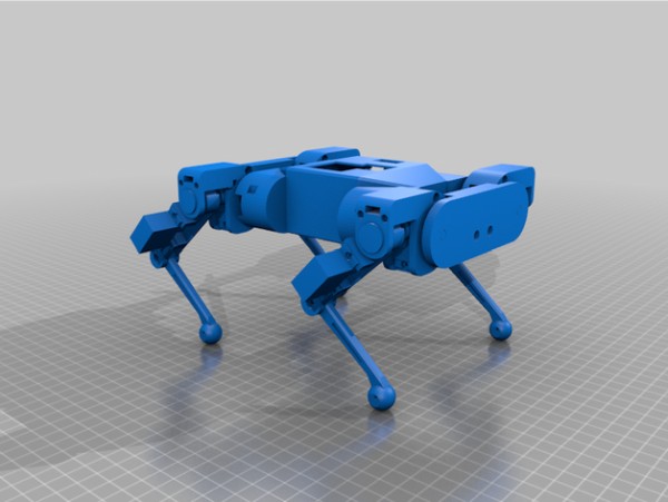
You can download the 3D-printed STL models here. The built robot shown here is printed in PLA. Suggested parameters for slicing the models to print are as follows. You may adjust them to fit the 3D printer you’re using.
- bottom/top thickness: 1mm
- shell thickness: 1.2mm
- layer height: 0.2mm
- infill density: 10%
- support: yes
- adhesion type: skirt or brim
Step 2: Hardware/Electronic Components
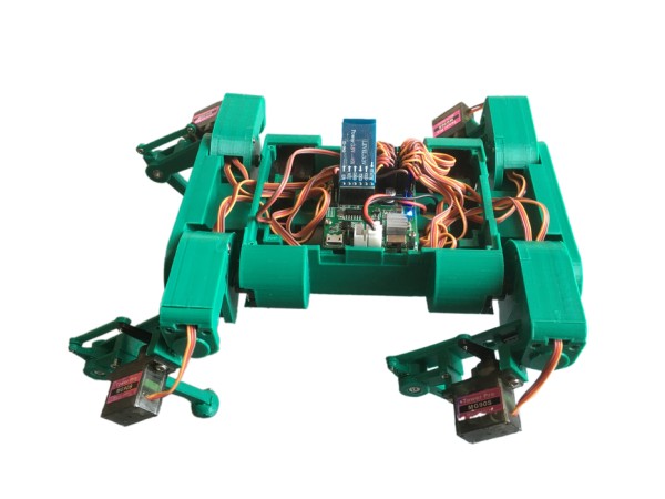
To build this robot you need the following hardware and electronic components:
- a HuaDuino board, it is Arduino Nano compatible with enhanced features. It integrates everything on a single PCB. It’s a lot easier for people to make a bot with it. Embedded battery charging circuit, battery charging is more convenient. It can be found on Amazon. See the full product description here, highly recommend you read it. It will save you trouble in using it.
- a single 3.7V 18650 lithium ion battery with XH2.54 connector.
- 12 x Tower Pro MG90s or compatible clone servos.
- a 5V buzzer
- a Bluetooth module, see below for details
- a female-female du point wire or anything you can figure out for connecting two pins
- some m2x6, m2x10 tapping screws
- some M3x6,M3x14,M3x20 flat head screws and M3 nuts
Bluetooth Module
- an HC-06, HC-05, and SPP-CA classic Bluetooth 4.0 SPP module, if you use this type of Bluetooth module; must use the virtual-gamepad-SPP Android app for control; the baud rate must be set to 115200; see this tutorial to configure the baud rate using AT commands;
- Or a BT-05 CC2540 Bluetooth LE module. There are many BLE modules named differently, but they are built with a CC254x chip. Examples such as HM-10 and CC41-A are the typical ones you can find in the market. Since the firmware is different, the AT command set may vary too. You may use this code to identify them. To work with the robot code and the apps, the baud rate is required to be set to 115200; service UUID must be set to 0xDFB0 and characteristic UUID must be set to 0xDFB1 using the AT commands. Below is the code intended to do that automatically but it may not work if you have different to use here.
The following stand-alone Arduino program issues AT commands setting BT-05 BLE module service UUID, characteristic UUID, and baud rate, assuming the BLE default baud rate is 9600.
void setup() {
  Serial.begin(9600); //change to fit your ble initial baud_rate, usually is 9600
  Serial.println("AT+UUID0xDFB0\r"); //  set service UUID
  delay(50);
  Serial.println("AT+CHAR0xDFB1\r"); // set characteristic UUID
  delay(50);
  Serial.println("AT+BAUD8\r");  // set baud rate to 115200
}
void loop() {}
Step 3: Software – Upload Robot Firmware
Robot Firmware –
Download this zip package and upload the firmware to HuaDuino as the video shows. The source code is in Github, check out the Lassie branch and look at the source_arduino folder.
Control Apps –
- goBLE iOS app on Apple Store; for Bluetooth LE module
- virtual-Gamepad-BLE Android app for Bluetooth LE module; compatible to Android 5.0 and latest.
- virtual-gamepad-SPP Android app for HC-06, HC-05 and SPP-CA classic Bluetooth 4.0 SPP module; compatible to Android 4.0 and above
Step 4: Wiring
-
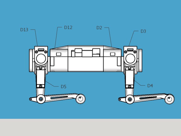
By uploading the firmware to HuaDuino, connecting A6 to the 5V pin with a dupoint wire and attaching servos to the designated pins will position all servos at the default angle, resulting in the robot assuming a posture similar to the figures shown below. The default angle is the angle of reference needed for proper execution of any type of movement.
2. After assembling the robot, take out the DuPoint wire to make sure it stands upright as the third finger; otherwise, you will need to readjust the servo.
Servo Pins –
- front right shoulder servo -> D2
- front right upper joint servo -> D3
- front right lower joint server -> D4
- back right shoulder servo -> D12
- back right upper joint servo -> D13
- back right lower joint server -> D5
- front left shoulder servo -> D9
- front left upper joint servo -> D8
- front left lower joint server -> D6
- back left shoulder servo -> D10
- back left upper joint servo -> D11
- back left lower joint server -> D7
Buzzer Pin –
- positive -> A2
- negative -> GND
Bluetooth Module –
- 6-pins socket
Step 5: Assembly – Body
To do this step the firmware must be loaded to HuaDuino. The model with the [R] mark is a set for the right side.
- connect the dupoint between the A6 and 5V pins for setting servos to the default angle
- connect Buzzer A2 and Gnd
- front right shoulder servo – D2
- back right shoulder server – D12
- front left shoulder servo – D9
- back left shoulder servo – D10
Source: Ez Arduino 12 DOF Quadruped Robot – Robot Dog Lassie
- What 3D printing settings are suggested?
bottom/top thickness 1mm, shell thickness 1.2mm, layer height 0.2mm, infill 10%, support yes, adhesion skirt or brim. - Which microcontroller board is used?
HuaDuino, an Arduino Nano compatible board with built-in features and battery charging circuit. - How many servos are required and which model?
12 servos, Tower Pro MG90s or compatible clones. - What battery is required?
A single 3.7V 18650 lithium ion battery with XH2.54 connector. - Which Bluetooth modules are supported?
HC-06, HC-05, SPP-CA classic modules or BT-05 CC2540-based BLE modules (examples HM-10, CC41-A). - What baud rate must Bluetooth use?
Baud rate must be set to 115200 for compatibility with the robot code and apps. - Which apps control the robot?
goBLE iOS for BLE, virtual-Gamepad-BLE Android for BLE, and virtual-gamepad-SPP Android for classic SPP modules. - What pin is the buzzer connected to?
Positive to A2 and negative to GND. - How are servos wired to HuaDuino pins?
Servos wired as listed: front right shoulder D2, front right upper D3, front right lower D4, back right shoulder D12, back right upper D13, back right lower D5, front left shoulder D9, front left upper D8, front left lower D6, back left shoulder D10, back left upper D11, back left lower D7. - How do you set servos to default angle before assembly?
Upload firmware, connect a DuPont wire between A6 and 5V to position servos at the default angle, then remove the DuPont wire after assembling.