Summary of Arduino Cyclone Reaction Time Game
Summary: This project builds a Cyclone-style arcade game and a reaction-timer using an Arduino Uno, an MCP23017 I/O expander, and an LCD. LEDs arranged as red/yellow/green indicate game states; two buttons switch modes and register player input. Cyclone mode cycles LEDs and rewards correct timing by increasing speed and level; Reaction mode measures reaction time after randomized delay. Code uses Adafruit MCP23017 and LiquidCrystal_I2C libraries, with functions for gameplay, scoring, and LED feedback.
Parts used in the Cyclone Reaction Time Game:
- Arduino Uno
- LCD Screen (I2C LiquidCrystal compatible)
- MCP23017 serial port expander
- 2 pushbuttons
- LEDs in differing colors (red, green, yellow; 3mm and 5mm used)
- Resistors: 100 ohm
- Resistors: 150 ohm
- Resistors: 10k ohm (for port expander and buttons)
- Jumper wires
- Breadboard
- A willing contestant (player)
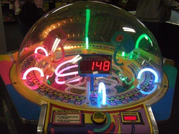
In this instructable, we walk through how I made a “Cyclone” – type arcade game using an Arduino. This game also includes a reaction timer mode. Let’s get started!
A list of things you will need:
- Arduino Uno
- LCD Screen
- MCP23017 serial port expander
- 2 pushbuttons
- LEDs of differing colors (I used 3mm and 5mm LEDs in red, green, and yellow)
- Resistors
- 100 and 150 ohm for LEDs
- 10k ohm for port expander and buttons
- Lots of jumper wires
- A willing contestant
Step 1: Wiring Up Your Breadboard and Accessories
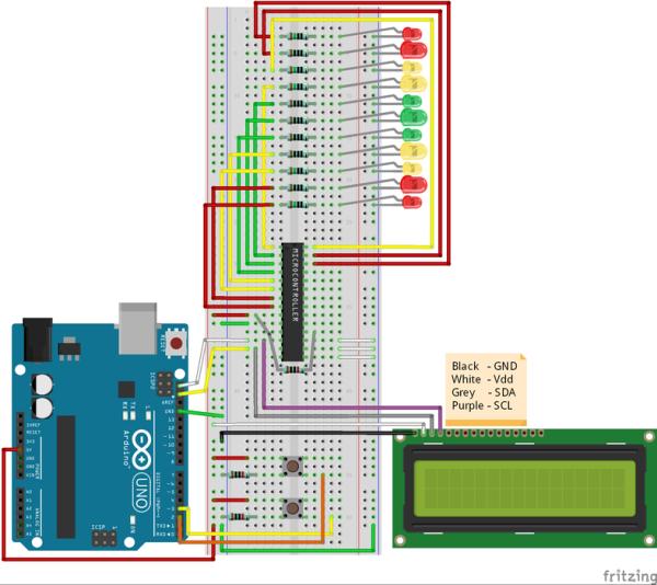
Connect the Arduino to all of the LEDs on the breadboard using the port expander shown in the first photo, where the “Microcontroller” chip is the MCP23017 port expander. Furthermore, establish a connection between the Arduino and the LCD screen. Make sure to adjust the screen’s contrast correctly by using the potentiometer located at the rear of the device.
Step 2: Coding!
Here is the code I wrote for this project. Note: you must download the appropriate libraries for the MCP23017 port expander (can be found on Adafruit) and your specific LCD screen.
I have included comments that explain most parts of the code. Feel free to comment if you have questions, and I will do my best to answer them.
#include <adafruit_mcp23017.h>
//Including MCP23017 port expander and LCD libraries

#include <liquidcrystal_i2c.h>
//can be downloaded from Adafruit

LiquidCrystal_I2C lcd(0x3f, 16, 2);
//These two lines create lcd and mcp objects
Adafruit_MCP23017 mcp;const int led1 = 15;                          //Initializing pin numbers as integers
const int led2 = 14;
const int led3 = 13;
const int led4 = 12;
const int led5 = 11;
const int led6 = 10;
const int led7 = 9;
const int led8 = 8;
const int led9 = 7;
const int led10 = 6;
const int led11 = 5;
const int buttonPin = 3;
const int modePin = 2;
boolean mode = true;
//These two booleans are used to change the mode from Cyclone to Reaction,
boolean pass = true;
//and to check for early button presses in Reaction mode

int chaseDelay = 100;
/This section initializes a bunch of variables used later in the code
int level = 0;
int hiScore = 0;
long reactionTime = 0;
long reactionStart = 0;
long hiReact = 999;
long adjust = 0;
int i = 0;

void setup() {
//This block runs only once at the start of the program
  Serial.begin(9600);
//Begin serial monitor communication
  lcd.begin();
//Turn on the LCD screen, and its backlight
  lcd.backlight();
  pinMode(buttonPin, INPUT);
//Setting the button pins as inputs
  pinMode(modePin, INPUT);
  mcp.begin();
//Begins communication through the MCP23017 port expander
  mcp.pinMode(led1, OUTPUT);
//Setting the pins associated with the ledX variables to outputs
  mcp.pinMode(led2, OUTPUT);
  mcp.pinMode(led3, OUTPUT);
  mcp.pinMode(led4, OUTPUT);
  mcp.pinMode(led5, OUTPUT);
  mcp.pinMode(led6, OUTPUT);
  mcp.pinMode(led7, OUTPUT);
  mcp.pinMode(led8, OUTPUT);
  mcp.pinMode(led9, OUTPUT);
  mcp.pinMode(led10, OUTPUT);
  mcp.pinMode(led11, OUTPUT);
}

void loop() {
  attachInterrupt(digitalPinToInterrupt(modePin), modeToggle, RISING);          //This line assigns the modePin as an interrupt, running the modeToggle function whenever the mode button is pressed
  if (mode) {                                                                  //If the mode is set to true, Cyclone begins
    lcd.setCursor(0, 0);
//This block prints text on the LCD screen
    lcd.print(" CYCLONE!  HS:" + String(hiScore) + "   ");
    lcd.setCursor(0, 1);
    lcd.print("Current Level:" + String(level));
    cyclone();
  } else {                                                                     //If the mode is set to false, Reaction begins
    lcd.setCursor(0, 0);
    lcd.print("REACTION! HS:" + String(hiReact) + "     ");
    lcd.setCursor(0, 1);
    lcd.print("Last Time:" + String(reactionTime) + "          ");
    if (digitalRead(modePin) == 1) {
      mode = true;
    }
    reaction();
  }
}

void modeToggle() {
//This is the modeToggle function which switches the mode
  mode = !mode;
}

void cyclone() {
//Cyclone function, which cycles through all the LEDs in order,
  for (i = 5; i <= 15; i++) {
//and waits for a button press
    mcp.digitalWrite(i, 1);
    if (i == 10 && digitalRead(buttonPin) == 1) {
//If the button is pressed at the same time as the middle green LED,
      goodBlink();
//the goodBlink function is triggered and the game resets
      i = 5;
      break;
    } else if (digitalRead(buttonPin) == 1) {
//If the button is pressed any other time,
      badBlink();
//the badBlink function is triggered and the game resets
      i = 5;
      break;
    }
    delay(chaseDelay);
    mcp.digitalWrite(i, 0);
  }
}

void goodBlink() {
//When this function is triggered, the user has successfully hit the green LED
  chaseDelay -= 10;
//The delay between LED flashes is decreased by 10ms, making the game harder
  level ++;
//The shown "level" increases by 1
  if (level > hiScore) {
//If the level is above the hi score, the hi score goes up
    hiScore = level;
  }
  for (int j = 1; j <= 5; j++) {
//This for loop blinks all the LEDs 5 times
    mcp.digitalWrite(5, 1);
    mcp.digitalWrite(6, 1);
    mcp.digitalWrite(7, 1);
    mcp.digitalWrite(8, 1);
    mcp.digitalWrite(9, 1);
    mcp.digitalWrite(10, 1);
    mcp.digitalWrite(11, 1);
    mcp.digitalWrite(12, 1);
    mcp.digitalWrite(13, 1);
    mcp.digitalWrite(14, 1);
    mcp.digitalWrite(15, 1);
    delay(250);
    mcp.digitalWrite(5, 0);
    mcp.digitalWrite(6, 0);
    mcp.digitalWrite(7, 0);
    mcp.digitalWrite(8, 0);
    mcp.digitalWrite(9, 0);
    mcp.digitalWrite(10, 0);
    mcp.digitalWrite(11, 0);
    mcp.digitalWrite(12, 0);
    mcp.digitalWrite(13, 0);
    mcp.digitalWrite(14, 0);
    mcp.digitalWrite(15, 0);
    delay(250);
  }
}

void badBlink() {
//When this function is triggered, the user missed the green LED
  chaseDelay = 100;
//The delay and level are reset to their default values
  level = 0;
  if (level > hiScore) {
    hiScore = level;
  }
  for (int k = 1; k <= 5; k++) {
//This for loop blinks just the red LEDs 5 times
    mcp.digitalWrite(5, 1);
    mcp.digitalWrite(6, 1);
    mcp.digitalWrite(14, 1);
    mcp.digitalWrite(15, 1);
    delay(150);
    mcp.digitalWrite(5, 0);
    mcp.digitalWrite(6, 0);
    mcp.digitalWrite(14, 0);
    mcp.digitalWrite(15, 0);
    delay(150);
  }
  mcp.digitalWrite(i, 0);
}

void reaction() {
//This function runs the reaction game
  mcp.digitalWrite(5, 1);
//The game begins with all the red LEDs on
  mcp.digitalWrite(6, 1);
  mcp.digitalWrite(14, 1);
  mcp.digitalWrite(15, 1);
  reactionStart = millis();
//The time in milliseconds is stored as reactionStart
  while (millis() - reactionStart < 3000) {
//and the game waits for 3 seconds, while also
    if (digitalRead(buttonPin) == 1) {
//constantly checking for an early button press
      pass = false;
//If you press the button early, the "pass" boolean is set to false
    }
//and the game skips to earlyBlink
  }
  if (pass) {
//The red LEDs turn off, and yellow LEDs are turned on
    mcp.digitalWrite(5, 0);
    mcp.digitalWrite(6, 0);
    mcp.digitalWrite(14, 0);
    mcp.digitalWrite(15, 0);
    mcp.digitalWrite(7, 1);
    mcp.digitalWrite(8, 1);
    mcp.digitalWrite(12, 1);
    mcp.digitalWrite(13, 1);
  } else {
    earlyBlink();
  }
  reactionStart = millis();
  long rando = random(500, 5000);
//The game then waits for a random delay between .5 and 5 seconds
  Serial.println(rando);
//Printing out the delay on the serial monitor, for testing purposes
  while ((millis() - reactionStart) < rando) {
//Again waiting for an early button press
    if (digitalRead(buttonPin) == 1) {
      pass = false;
    }
  }
  if (pass) {
//If you dont press early, the yellow LEDs turn off and the green turn on
    mcp.digitalWrite(7, 0);
    mcp.digitalWrite(8, 0);
    mcp.digitalWrite(12, 0);
    mcp.digitalWrite(13, 0);
    mcp.digitalWrite(9, 1);
    mcp.digitalWrite(10, 1);
    mcp.digitalWrite(11, 1);
    reactionTime = 0;
//The clock begins ticking right when the green LEDs turn on
    reactionStart = millis();
    while (digitalRead(buttonPin) == 0) {
//The game hangs while it waits for you to react and press the button
    }
    reactionTime = millis() - reactionStart;
    lcd.setCursor(0, 1);
    lcd.print("Last Time:" + String(reactionTime) + "   ");
//After you press the button, the game stores and prints out your reaction time, in milliseconds
  } else {
//This else statement runs if you pressed a button early at any point in the game
    earlyBlink();
  }
  mcp.digitalWrite(9, 0);
  mcp.digitalWrite(10, 0);
  mcp.digitalWrite(11, 0);
  delay(1000);
  if (reactionTime < hiReact && reactionTime != 0) {
    hiReact = reactionTime;
  }
  pass = true;
}

void earlyBlink() {
//This function blinks the red LEDs 3 times if you press the button early, then restarts the game
  for (int k = 1; k <= 3; k++) {
    mcp.digitalWrite(5, 1);
    mcp.digitalWrite(6, 1);
    mcp.digitalWrite(14, 1);
    mcp.digitalWrite(15, 1);
    delay(150);
    mcp.digitalWrite(5, 0);
    mcp.digitalWrite(6, 0);
    mcp.digitalWrite(14, 0);
    mcp.digitalWrite(15, 0);
    delay(150);
    mcp.digitalWrite(5, 0);
    mcp.digitalWrite(6, 0);
    mcp.digitalWrite(7, 0);
    mcp.digitalWrite(8, 0);
    mcp.digitalWrite(9, 0);
    mcp.digitalWrite(10, 0);
    mcp.digitalWrite(11, 0);
    mcp.digitalWrite(12, 0);
    mcp.digitalWrite(13, 0);
    mcp.digitalWrite(14, 0);
    mcp.digitalWrite(15, 0);
  }
}
Step 3: Play!
Once you compile the code and upload it to your Arduino, the game should run! (Assuming everything is wired correctly) Attached is a video showing gameplay of the project. I hope you enjoyed, and good luck!
Source: Arduino Cyclone Reaction Time Game
- What libraries are required to run the code?
The project uses the Adafruit MCP23017 library and a LiquidCrystal_I2C library for the LCD. - How are the LEDs connected to the Arduino?
The LEDs are connected to the MCP23017 port expander, which is interfaced to the Arduino. - Can the game measure reaction times?
Yes, the Reaction mode measures reaction time in milliseconds and displays Last Time and high score on the LCD. - How do you switch between Cyclone and Reaction modes?
A mode button connected to modePin toggles modes via an interrupt and switches gameplay. - What happens when you hit the correct LED in Cyclone mode?
The goodBlink function runs: level increases, chaseDelay decreases, LEDs blink, and hiScore updates if needed. - What happens if you press the button early in Reaction mode?
If pressed early the pass boolean becomes false and earlyBlink runs, blinking red LEDs and restarting the game. - How is difficulty increased in Cyclone mode?
chaseDelay is reduced by 10 ms each successful hit, making the LED chase faster and increasing level. - Do you need to adjust the LCD screen after wiring?
Yes, you should adjust the LCD contrast with the potentiometer on the rear of the screen.