Summary of Acoustic Radar Display
This article details the construction of an ultrasonic "radar-style" display using an Arduino Uno, a HY-SRF05/HC-SR04 sensor, and a 28BJY-48 stepping motor. The system rotates the sensor to detect objects, displaying azimuth and distance data on a Processing-based screen with red and blue indicators for primary and secondary echoes. Construction involves assembling parts inside a plastic container with custom aluminum mounting brackets and includes optional circuit modifications for multi-echo detection.
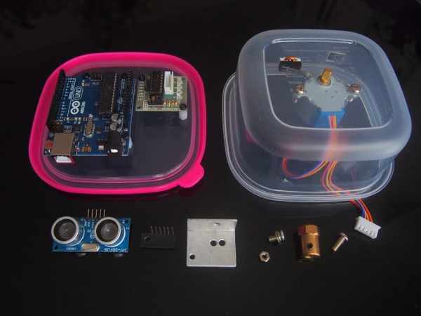
Parts used in the Ultrasonic Radar Display:
- Plastic food container
- Sub-miniature micro-switch
- Male header strip
- Female header strip
- 20 gauge aluminium sheet (40mm x 55mm)
- Nine-millimeter nylon spacers (tapped 3mm)
- Cable-ties
- 3mm x 6mm bolts
- 3mm nut
- 4mm x 10mm bolts
- 4mm nuts
- Arduino Uno R3 microcontroller with USB cable
- 28BJY-48 5 volt stepping motor with ULN2003 controller
- 5mm bore brass hex shaft to wheel coupler
- HYSRF05 or HC-SRF04 ultrasonic sensor
This instructable describes how to make an ultrasonic “radar-style” display using an Arduino microcontroller, an ultrasonic sensor, and a small stepping motor.
An optional sensor modification allows multiple objects to be detected with each ping.
Construction is simple … all you need are two drills, a sharp knife, a pair of side-cutters , and a soldering iron.
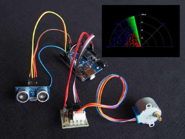
Photo 1 shows the basic parts. The “insert” shows a random-dot test pattern. Dots representing primary objects are shown in red … dots representing secondary objects are shown in blue.
Photo 2 shows the assembled unit.
Photo 3 shows an actual screen shot of seven objects. [1]
The video clip shows the unit in operation.
[1]
The azimuth and distance of each primary object are shown in red. Any echo from a secondary object is shown in blue. Without the sensor modification you will only see the red objects.
Since the sonic pulses expand in a cone-like manner, distant objects appear wider. The actual bearing of each object is the midpoint of each continuous (red or red/blue) line.
Continuous lines containing both red and blue dots are a single object, part of which is in shadow.
Step 1: Wiring Diagram
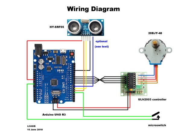
The wiring diagram is shown in photo1.
An optional modification is shown in photo2. This modification is the SAME for both the HC-SR04 and the HY-SRF05 ultrasonic sensors and allows multiple echos to be detected. [1]
[1]
For a full explanation see my instructable https://www.instructables.com/id/Enhanced-Ultraso…
If you have an HC-SR04, the integrated circuit to which you solder the wire is labelled U2
Step 2: Parts List
The following parts were obtained locally:
- 1 only plastic food container.
- 1 only sub-miniature micro-switch.
- 1 only male header strip (used for attaching wires from sensor).
- 1 only female header strip (used to mount sensor).
- 1 only piece of 20 gauge aluminium (scrap) sheet 40mm x 55mm.
- 6 only 9mm nylon spacers tapped 3mm.
- 3 only cable-ties.
- 13 only 3mm x 6mm bolts.
- 1 only 3mm nut.
- 4 only 4mm x 10mm bolts.
- 2 only 4mm nuts.
The following parts were obtained from https://www.aliexpress.com/
- 1 only Arduino Uno R3 microcontroller complete with USB cable.
- 1 only 28BJY-48 5 volt stepping motor complete with ULN2003 controller.
- 1 only 5mm bore brass hex shaft to wheel coupler for model cars.
- 1 only HY-SRF05 (or HC-SRF04) ultrasonic sensor.
Step 3: How It Works
Mechanical
All parts are housed inside a plastic food container. Power is obtained from your USB port.
The circuit comprises an Arduino, an ultrasonic sensor, a stepping-motor, and a micro-switch for moving the sensor to its “home” position. The micro-switch is necessary as it is not possible to rotate the stepping motor by hand due to its 64:1 internal gearing.
When first powered up the Arduino rotates the sensor to its “home” position, as determined by the micro-switch, then “polls” the display until it gets a response.
The 28BJY-48 stepping motor has a “stride angle” of 5.625/64 degrees which means that 1 degree steps are not possible (even though our graticule is labelled 0..180 degrees).
Fortunately, 180/stride-angle = 180*64/5.625 = 2048 which is evenly divisible by 8. If we increment a number from 0..2048 and divide by 8 there are 256 occasions when we get a remainder of zero … we simply send a “ping” whenever the remainder is zero. This equates to a “ping” every PI/256 radians or 0.703125 degrees.
Software [1]
The display then takes control and continually asks the Arduino to supply the following data:
- Azimuth
- Distance1
- Distance2
- Direction
The “distance(s)” for each “azimuth” are then displayed on the screen. The “direction” information is used to create the illusion of “dots” appearing behind the “beam” as it rotates.
The Arduino automatically moves to the next “ping” position whenever data is sent to the display.
[1]
The “Processing 3” software used for writing the display may be downloaded from https://processing.org/download/
Processing 3 supports 2D and 3D graphics and is very similar to the Arduino IDE (Integrated Development Environment). The main visual differences are a “graphics window” when the code is running and the use of a “draw()” function instead of the Arduino “loop()”.
Step 4: The Display
The Graticule
I chose to create a 180 degree graphics display as it provides a “radar shadow” in which to stand while experimenting. Such a display is also compatible with a servo motor should I wish to use one. A full 360 degree display can be obtained by tweaking the code.
The following photos explain how the graticule was created:
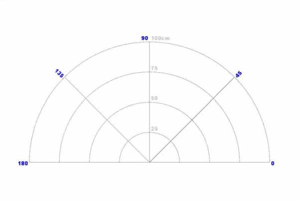
Photo 1
- The graticule comprises a number of “arcs” and “lines”. Angled labels are shown in this photo but were later dropped in favour of horizontal text which is easier to read.
Photo 2
- Shows a red line depicting the “beam”. The text in the label is now horizontal.
Photo 3
- The red line in photo 2 has been rotated 0..180 degrees through 256 azimuth positions. In this photo the outer parts of the graticule are not covered as the beam-width is too narrow. This results in some strange artifacts.
Photo 4
- Increasing the beam-width has eliminated these artifacts.
Photo 5
- Random dots have been introduced to represent primary (red) and secondary (blue) echos. The range, which can be changed, has been set to exactly 100cm to match the display. A fading beam pattern has also been introduced. The technique used to create this “fading beam” is explained further on.
Photo 6
- The color scheme has been changed to add a touch of realism.
Animation
The animated portions of the graphics display use 3D graphics to greatly simplify the code. To understand how this is possible let’s draw a “30 degree line” of constant radius from an XY start coordinate of (0,0).
2D graphics requires the use of sin(30) and cos(30) to calculate the XY end coordinates of the line:
X=cos(30)*radius = 0.866*radius
Y=sin(30)*radius = 0.5*radius
line(0,0,X,Y);
3D graphics doesn’t require the use of trigonometry. We simply rotate the XY grid coordinates about the Z-axis then draw a horizontal line …. no maths required!!!
pushMatrix();		//preserve our current grid coordinates
rotateZ(radians(30));	//rotate our XY grid coordinates about the Z-axis
line(0,0,radius,0);	//draw a “horizontal” line on the rotated grid
popMatrix();		//restore our grid coordinates
Either way works but this second method lends itself to “ping” intervals of PI/256 radians.
Fading Lines
The fading beam pattern uses a clever technique found at https://forum.processing.org/two/discussion/13189…
The beam is given its own virtual screen. Prior to drawing any line the “alpha” (opacity) of all previous lines is reduced by a small amount. Ultimately the earliest lines become invisible which gives the illusion of a fading “fan” pattern.
This virtual screen, which is never erased, is then merged with the contents of the main screen whenever the display is refreshed.
Step 5: Mounting Bracket
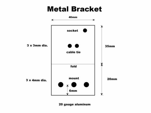
The drilling template for a suitable mounting bracket is shown in photo 1.
Position the two outer “mount” holes below the transmit (T) and receive (R) sensors. I find that best results are obtained if the sensor rotates around the receive (R) sensor rather than midway between the two sensors. The three holes allows you to experiment.
Details of how to “cut and fold” aluminium may be found in my instructable https://www.instructables.com/id/How-to-Cut-Fold-…
Step 6: Assembly
USB cable-hole
Do not try and drill a cable-hole for the USB connector though the side of the plastic container as plastic tends to split and chip. Instead, melt a hole using the tip of a hot soldering iron then trim with a sharp knife. Take care not to breath the fumes.
Shaft-extender
Replace one of the 4mm “grub-screws” in the shaft-extender with a 4mm x 10mm bolt. This bolt is used to activate the micro-switch.
Micro-switch
Position the micro-switch such that it is activated by the 4mm bolt when the shaft rotates in a clockwise direction.
I used two turns of 20 gauge copper wire to attach the micro-switch to the case as 2mm nuts and bolts were not readily available.
Remaining components
Layout is not critical. The motor shaft was positioned centrally. The Arduino and motor controller were mounted on nylon spacers which allow the wires to be tucked underneath.
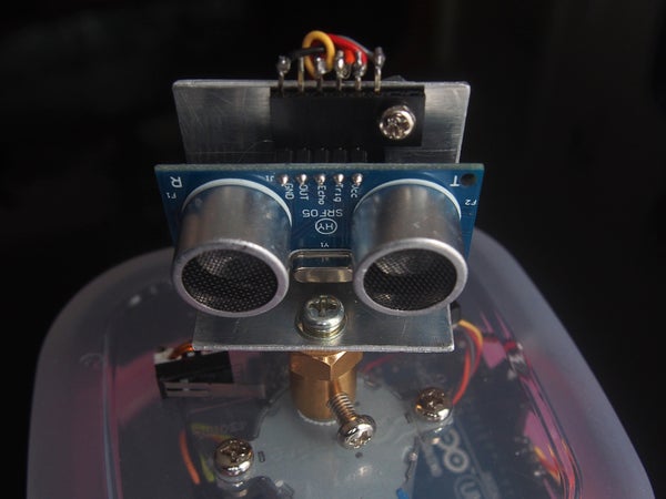
Mounting the sensor
Photo 1
- shows the sensor assembly. The HY-SR0F-5 socket has been fashioned from a female-header socket. All unwanted pins have been removed and a 3mm hole drilled through the plastic. The header is then attached to the bracket by means of a 3mm nut and bolt.
Photo 2
- shows a side view of the sensor assembly. The wires from the header are cable-tied to the bracket. This “strain-relief” prevents unwanted cable movement as the sensor rotates. Note also the “grey” wire attached to pin 10 of IC1. This wire is optional and feeds the secondary echos to the Arduino.
Attach the sensor assembly to the shaft extender after the micro-switch has operated following power-up. The shaft is then in its “home” position.
Step 7: Software Installation
Install the following code in this order:
Arduino IDE
Download and install the Arduino IDE (integrated development environement) from https://www.arduino.cc/en/main/software if not already installed.
Processing 3
Download and install Processing 3 from https://processing.org/download/
Acoustic Radar Sender [1]
Copy the contents of the attached file, “acoustic_radar_sender_2.ino”, into an Arduino “sketch”, save, then upload it to your Arduino Uno R3.
Close the Ardino IDE but leave the USB cable connected.
Acoustic Radar Receiver
Copy the contents of the attached file, “acoustic_radar_receiver.pde” into a Processing “Sketch”.
Bugfix
[1]
“acoustic_radar_sender_2.ino” fixes a “scan-creep” bug in “acoustic_radar_sender_1.ino” . My thanks to https://www.instructables.com/member/newtoeu/instr… for pointing it out.
Source: Acoustic Radar Display
- How does the system determine the home position?
The Arduino rotates the sensor until it activates a micro-switch which is necessary because the stepping motor cannot be rotated by hand due to its internal gearing. - Can multiple objects be detected with each ping?
Yes, an optional sensor modification allows the system to detect multiple echos, showing secondary objects in blue. - What software is required to run the display?
The project requires the Arduino IDE for the sender code and Processing 3 for the receiver graphics display. - How is the beam width adjusted to eliminate artifacts?
Increasing the beam-width in the code eliminates strange artifacts caused by narrow beam coverage at the outer graticule areas. - Does the display support a full 360-degree rotation?
The standard setup creates a 180-degree display, but a full 360-degree display can be obtained by tweaking the code. - What method is best for creating the USB cable hole?
It is best to melt a hole using a hot soldering iron tip rather than drilling, as drilling plastic tends to cause splitting and chipping. - Why are nylon spacers used for the motor and Arduino?
Nylon spacers allow the wires to be tucked underneath the mounted components for a cleaner layout. - How does the fading beam pattern work?
A virtual screen reduces the opacity of previous lines slightly before each refresh, causing older lines to fade out and creating a fan illusion. - What is the purpose of the grey wire attached to pin 10?
This wire is optional and feeds secondary echo data to the Arduino to enable multi-object detection. - How often does the system send a ping during rotation?
The system sends a ping every PI/256 radians, which equates to approximately 0.703125 degrees.