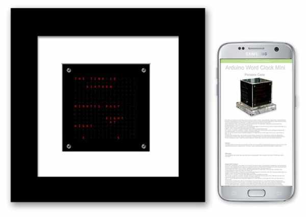
Arduino Word Clock Mini- Anniversary Clock
Relatively easy to build Word Clock using a Arduino Nano and four MAX7219 32mm Dot Matrix Display Modules
Choice of styles, picture frame or Perspex cube with various base options.
Specs
Mini Arduino Word Clock with minute resolution of time in words and linear display of seconds. Uses an Arduino Nano and Four MAX7219 32mm Dot Matrix Displays giving 256 LEDs the same as my large Word Clock
There are modes, digital clock, analogue clock, temperature & humidity, & also three games, Game of Life, Simon & Tetris.
The clock can be stand alone or run as a slave off a Master Clock if required. In stand alone mode the clock runs off it’s built in temperature compensated real time clock with an accuracy of ±2ppm from 0°C to +40°C
When running as a slave off a Master Clock time is synchronised on every 30 seconds past the minute. There is an option for PIR/Microwave Radar Sensor control so the clock automatically turns off when no one is in the room.
The Clock display measures 64mm x 64mm and is designed to be desk mounted although the picture frame version could go on a wall. There are touch pads in each corner to setup and control the clock. A mini USB socket allows software programming in situe.
Plugging in an Android phone/PC allows setting of the time and choice of what mode to display on startup. Time setting can also be carried out in the digital clock mode using the touch buttons.
The clock draws 20mA (all LEDs off) to 40mA (LEDs max brightness) from it’s 12v supply.
There is a choice of designs. Picture Frame Clock pic 1 or a Perspex Cube Clock pic2. Each design uses a different Veroboard layout but shares the same code.
Full details also available on my Word Clock Mini web site.
Credits
This clock is a miniaturised version of my Word Clock and is in turn based on the original Word Clock by Wouter Devinck full details on this Instructable and the “Catalan” Pijuana Word Clock software based on Wouter Devinck’s clock (this is a fork off the original Wouter Devinck design) here GitHub.
Step 1: Clock Type Examples
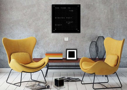
Picture Frame Word Clock
Picture 1.
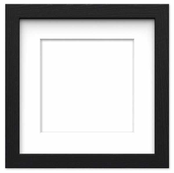
The picture frame clock is the easiest and cheapest of the clocks to build. it just requires a plain black 6″x6″ (150x150mm) picture frame with a white card mount reducing the frame size down to 4″x4″. Enough to see the display with a bit of space all around. The Perspex glass was replaced with real 2mm glass as the Perspex was attracting too much dust.
On the rear of the frame I have added a box from thin plywood 170mm x 170mm x 40mm deep. You may be able to get a shadow box with the same size box on the back.
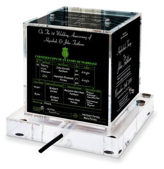
Perspex Cube Word Clock
Picture 2.
The Perspex Cube clock is a bit more tricky to build as there are 2 Veroboards to build along with a number of holes to be drilled in the Perspex case and base. An cheaper MDF base could also be built and this can also house a PIR instead of a Radar sensor in the main case and the DHT22 temperature & humidity sensor.
The Perspex case and 20mm Perspex base each cost more than the Picture frame alone.
Picture 3 shows the relative sizes of the Mini word clocks compared to my original clock.
Step 2: Perspex Case Option
Perspex Case Option
With Radar Controlled display and PWM LED backlight.
There are two case styles a Picture Frame or a Perspex Cube.
The 100mm x 100mm Perspex Cube can be stand alone or have a MDF base to house the Temperature/Humidity sensor and also a PIR to blank the display when no one is in the room. A 20 mm thick Perspex base can also be fitted see picture 1 above. In this case the temperature/humidity sensor is fitted inside the case along with a Microwave Radar Sensor RCWL0516 to sense movement.
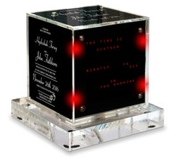
Picture 2. Transparencies are fitted to the sides, rear and top and can be plain or have messages printed as required. These Inkjet Transparencies made from the original Wedding certificate and original invites. Fitted to sides of the clock these are illuminated by the on board LED.
Picture 3. A LED in the rear illuminates the transparencies at night controlled by the PIR/Radar sensor as required.
Step 3: Picture Frame Option
Picture Frame Option
Picture 1 I have used a plain black 6″x6″ (150x150mm) picture frame with a white card mount reducing the frame size down to 4″x4″. Enough to see the display with a bit of space all around. The Perspex glass was replaced with real 2mm glass as the Perspex was attracting too much dust.
Picture 2 On the rear of the frame I have added a box from thin plywood 170mm x 170mm x 40mm deep.I have used Mitre Glue (picture 3) to fix the box together then cut and glued corner braces from wood off cuts.
The box lid is fixed by small wood screws to these corner braces. The box is fixed to the frame with 2 angle brackets I cut from some angled aluminium.
The touch sensors can be seen at the rear of the frame with Perspex covers.
Wooden feet are cut from blocks of wood and hold the frame at an angle on the desk or table. Rubber feet are glued to the wooden block feet to stop the clock slipping on the desk or table top.
As this clock is for a first wedding anniversary a label is attached to the back behind a Perspex sheet. Not shown in this photo are the 12v power lead and short USB cable coming out of the rear of the box.
Picture 4. The dot matrix displays are fixed to show through the front of the card mounts. On the completed clock
the LEDs are fixed behind the letter mask and a sheet of dark neutral density Perspex sheet and will only be visible when an LED is on illuminating a letter on the mask.
Step 4: Touch Button Controls
On the Perspex case version there are 5 Touch Buttons. One is located on the back of the case and just sets the backlight On or Off.
The other four touch buttons are located around the four corners of the sides of the display. Picture 3 view from rear of case with case transparencies removed showing touch button locations. These buttons are repeated on the other side as well.
Unless in a sub menu the “top left” button steps to the previous display mode and the “top right” button steps to the next display mode.
When a touch location on the case is touched the LED indicator on the touch button lights while you are touching it to indicate it is active. Picture 2 touch buttons glowing behind the main display to show their locations. The buttons only light when touched, normally they are off.
Picture 1 Lopped animation showing touch buttons in use.
1 top left button steps from “Word Clock” mode to the previous mode “Message display” 2 top right button steps from “Message display” mode back to next mode “Word Clock” 3 in “Word Clock” mode pressing the bottom right button turns the PIR/Radar Module Off “PIR NO” is displayed for 2 seconds 4 in “Word Clock” mode pressing the bottom left button turns the PIR/Radar Module On “PIR ON” is displayed for 2 seconds
Picture 4 The picture frame version has four touch buttons located on the rear of the main frame on each corner.
Buttons are activated by gently squeezing a corner between your thumb and index finger.
Step 5: Touch Button Controls
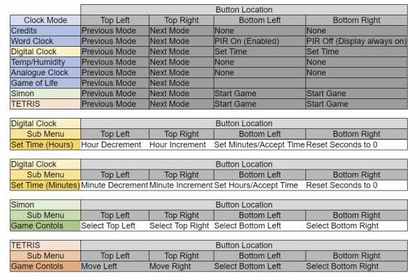
The touch buttons have different functions depending on what mode the clock is in, see chart below.
The perspex Clock has a 5th button in the rear of the case to turn the backlight LED On & Off
Source: Arduino Word Clock Mini