As a long time lurker I finally decided this project was worthy of a write up (also I’m killing for an instructables tshirt). I love this site and hope you enjoy this project.
IMPORTANT!
Just a quick heads up, there are optional steps in this build. Your horn will be fully functional by step6 however I have included further options to monitor battery levels, change your Bluetooth device name and more!
Also if anything isnt clear please let me know! I’ll amend this write up with anything I may have missed.
Step 1: Tools & Materials
Will keep the links updated if any go offline.
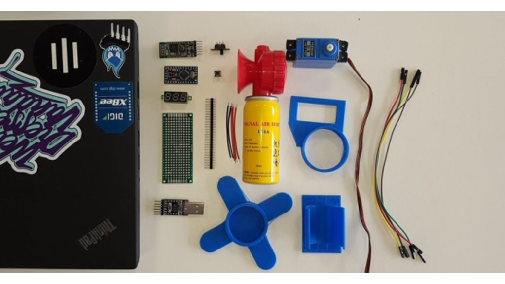
Components Required:
- Arduino Pro Mini 3.3v 8mhz or 5v 16mhz (link)
- UART TTL Programmer (link)
- HC-05 Bluetooth Module (link)
- Header Pins [about ~25 should do] (link)
- Hookup Wire (enough to connect the pins on the breadboard)
- Air Horn 134A (link)
- 180 Degree Servo Motor (link)
- Solder-able breadboard [cut to size] (link)
- 4 x AA Battery Clip [Not Pictured] (link)
- 4 x AA Batteries (Not Pictured)
Optional Extras:
Tools Required:
- Soldering Iron + Solder
- Hot Glue Gun
- Flush Cutters
- 3D printer (or 3d printing service online)
Step 2: Flashing the Arduino
First of all you’ll want to flash your Arduino. If it didn’t come with the header pins soldered you’ll need to solder the 6 pins labeled:
GND, GND, VCC, RXI, TXO, DTR (these will all be in a row on the bottom of your dev board)
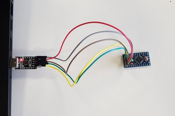
Once you have soldered the pins you’ll need to connect them to your FTDI Programmer as follows:
FTDI —-> Arduino
DTR —-> DTR
RXD —-> TXO
TXD —-> RXI
+5v —-> VCC
GND —-> GND
Now upload our test code (you can find the code here also):
#include <Servo.h><br>#include <SoftwareSerial.h><br><br><p>Servo hornServo;  // create servo object to control a servo<br>SoftwareSerial BT(10, 11);
char a; // stores incoming character from other device
int pos = 0;    // variable to store the servo position</p><p>void setup() {<br>
  BT.begin(9600);
  BT.println("Air Horn Active");
  hornServo.attach(9);  // attaches the servo on pin 9 to the servo object
  hornServo.write(10);  // sets the servo position</p><p>}</p><p>void loop() {<br>
if (BT.available())
  {
    a=(BT.read());</p><p>    if (a=='1')
    {
    hornServo.write(90);              // tell servo to go to position in variable 'pos'
    delay(15);
    BT.println("");
    delay(350);
    hornServo.write(10);              // tell servo to go to position in variable 'pos'
    delay(15);
    }

    if (a=='2')
    {
    hornServo.write(90);              // tell servo to go to position in variable 'pos'
    delay(15);
    BT.println("");
    delay(400);
    hornServo.write(10);              // tell servo to go to position in variable 'pos'
    delay(15);
    }

    if (a=='3')
    {
    hornServo.write(90);              // tell servo to go to position in variable 'pos'
    delay(15);
    BT.println("");
    delay(500);
    hornServo.write(10);              // tell servo to go to position in variable 'pos'
    delay(15);
    }</p><p>    if (a=='4')
    {
    hornServo.write(90);              // tell servo to go to position in variable 'pos'
    delay(15);
    BT.println("");
    delay(600);
    hornServo.write(10);              // tell servo to go to position in variable 'pos'
    delay(15);
    }

    if (a=='?')
    {
      BT.println("Send '1' for a sharp blast");
      BT.println("Send '2' for a longer blast");
      BT.println("Send '3' for a decent blast");
      BT.println("Send '4' for a deafening blast");
    }
  }
}</p>
Step 3: Assembling the Board (Placement and Power Soldering)
This step will require a few connections and some patience however it is quite straight forward.
NOTE: you can also perform this step on a regular breadboard without soldering however it will render your final product a little less portable.
Placement:
Components for this step:
- Arduino
- BT Module
- 3 Male Header Pins
- Wire
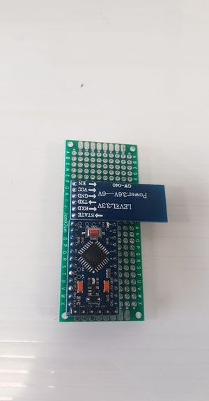
We must place the flashed Arduino and the Bluetooth module (HC-05) on the breadboard in any orientation we see fit. Ensure that the breadboard you are using does not group and bridge rows of pins. On the PCB-Way breadboard I used, each pin was independent.
Solder the following pins together:
Wire Out –> Arduino –> BT Module –> Header Pin
Red Wire –> VCC –> VCC –> Middle Pin
Black Wire –> GND –> GND –> Bottom Pin
Note: there are 2 GND pins on the Arduino, you can use either.
The final image depicts where I have soldered a single black and red wire to the right of the Arduino for the power connection.
Source: Bluetooth Air Horn