
Summary of CREATE +/-12V SPLIT RAIL FROM A 5V BIAS
### Summary This article addresses the challenge of maintaining analog sensor accuracy as digital systems lower supply voltages. It proposes generating a higher-voltage split-rail bias (±12V) from a low single-rail 5V supply using a flyback switch-mode regulator. The design utilizes a Texas Instruments LM5001 IC and a center-tapped transformer to create stable positive and negative rails, reducing leakage currents and improving signal-to-noise ratio compared to virtual ground methods.
Parts used in the Split Rail Bias Generator:
- Texas Instruments LM5001 switch-mode regulator
- Center-tapped transformer T1
- Diode D3
- Diode D2
- Diode D4
With digital semiconductor technology driving system power supplies to lower voltages for higher performance and lower system power, sensitive analog sensor circuits face a growing problem. Much of the inherent noise created in the early stages of an analog sensor signal path is independent of the amplifier bias voltage, so using a higher bias voltage yields better accuracy and performance than a lower bias. With supply voltages dropping, then, designers must tolerate the loss of accuracy (SNR) due to the lower available voltage or derive a higher voltage bias from the available system supply.
In addition to the voltage, designers need to consider the ground. In many cases the sensor circuit must have bias voltages both above and below signal ground. That signal ground can be either a true system ground or a virtual ground created at the midpoint of a single-rail power supply. Using a true system ground requires “split-rail” biasing (±V), but yields improved performance as a result of reduced leakage currents and reduced variations in a virtual ground, both of which affect measurement accuracy.
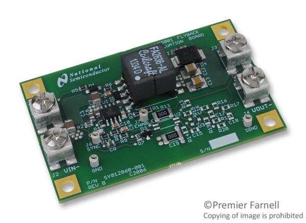
To obtain the best performance from the analog front end, then, designers need a method of creating a higher voltage split-rail bias from a lower-voltage single-rail supply. One way to create this split-rail voltage is to use a switch-mode regulator IC in concert with a small transformer. This forms a flyback design that uses less than one square inch of board space.
The circuit of Figure 1 boosts a nominal 5-V single-rail supply (4.5 to 5.5 V) to a low-noise, ±12-V bias and can be adapted to develop other voltages such as ±15 V. The design uses a Texas Instruments LM5001 (U1) switch-mode regulator that integrates a pulse-width modulation (PWM) generator, a switching transistor, a voltage reference, and an error amplifier that controls the PWM duty cycle based on a comparison between the reference and the feedback signal on pin 6.
The regulator switches current through the primary of center-tapped transformer T1, and the PWM duty cycle determines the output voltage at the secondary. Diode D3 and its attached components serve as a snubber to minimize transient noise and ringing on the transformer input when the regulator’s internal switch opens. Diodes D2 and D4 serve as half-wave rectifiers for the transformer’s output.
Read more: CREATE +/-12V SPLIT RAIL FROM A 5V BIAS
- Why do designers need a higher voltage bias for analog sensors?
Using a higher bias voltage yields better accuracy and performance because inherent noise in early analog stages is independent of amplifier bias voltage. - What problem arises when system power supplies drop to lower voltages?
Designers face a loss of accuracy measured as Signal-to-Noise Ratio due to lower available voltage or must derive a higher voltage bias from the existing supply. - How does a true system ground compare to a virtual ground?
A true system ground requires split-rail biasing but yields improved performance through reduced leakage currents and reduced variations compared to a virtual ground. - What circuit configuration creates a split-rail voltage from a single-rail supply?
A flyback design using a switch-mode regulator IC in concert with a small transformer forms this configuration. - What components are integrated inside the LM5001 regulator?
The regulator integrates a pulse-width modulation generator, a switching transistor, a voltage reference, and an error amplifier. - What is the function of diode D3 in the circuit?
Diode D3 and its attached components serve as a snubber to minimize transient noise and ringing on the transformer input. - How do diodes D2 and D4 function in the output stage?
Diodes D2 and D4 serve as half-wave rectifiers for the transformer’s output. - What is the nominal input voltage range for this specific circuit design?
The circuit boosts a nominal 5-V single-rail supply with a range of 4.5 to 5.5 V. - Can this design be adapted for other voltage levels?
Yes, the design can be adapted to develop other voltages such as ±15 V.
