
Summary of LITHIUM COIN CELL CHARGER FOR RECHARGEABLE COIN BATTERIES
This article describes a versatile USB-powered charger designed for Lithium Coin Cell rechargeable batteries (CR2016, CR2025, CR2032). The board utilizes dual chip options, specifically the BQ21040 or MCP73831 ICs, with testing performed on the BQ21040. It features programmable charge currents up to 800 mA via an external resistor and includes LED indicators for charge status and cycle monitoring. The device supports conditioning, constant current, and constant voltage charging phases while managing temperature and overvoltage protection.
Parts used in the Lithium Coin Cell Charger:
- Lithium Coin Cell Rechargeable Batteries (CR2016/CR2025/CR2032)
- Battery Holder
- USB Port Interface
- D3 Power LED
- D1 Charge Cycle LED
- BQ21040 IC (Texas Instruments)
- MCP73831 IC (Microchip)
- External Resistor R2
- Pull-up Resistor for STATUS terminal
- Series Resistor for visual indication LED
This versatile charger has been designed to charge Lithium Coin Cell Rechargeable CR2016/CR2025/CR2032 Coin Batteries. Just insert the battery to the holder, and plug in to any USB port to recharge, D3 Power LED, D1 LED indicates the charge cycle. The board has been designed to use dual chips, either BQ21040 IC from Texas instruments or MCP73831 from Microchip however the board is tested with BQ21040 IC.
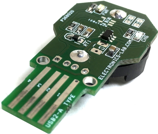
Programmable Charge Current using External Resistor up to 800 mA (default set to 50mA), follow formula bellow to set the desired current.
An external resistor R2 is used to Program the Output Current (50 to 800 mA) and can be used as a current monitor.
RISET = KISET / IOUT
Where
- IOUT is the desired fast charge current;
- KISET is a gain factor found in the electrical specification (1)
For greater accuracy at lower currents, part of the sense FET is disabled to give better resolution. Figure 1 shows the transition from low current to higher current. Going from higher currents to low currents, there is hysteresis and the transition occurs around 0.15 A.
For host monitoring, a pull-up resistor is used between the STATUS terminal and the VCC of the host and for a visual indication a resistor in series with an LED is connected between the STATUS terminal and a power source. First charge after Input supply applied LED will be ON and LED will be OFF when OVP/SLEEP condition.
BQ21040 – SINGLE-INPUT, SINGLE CELL LI-ION AND LI-POL BATTERY CHARGER
The bq21040 device is a highly integrated Li-Ion and Li-Pol linear battery charger device targeted at space limited portable applications. The device operates from either a USB port or AC adapter. The high input voltage range with input overvoltage protection supports low-cost unregulated adapters. The bq21040 has a single power output that charges the battery. A system load can be placed in parallel with the battery as long as the average system load does not keep the battery from charging fully during the 10 hour safety timer. The battery is charged in three phases: conditioning, constant current and constant voltage. In all charge phases, an internal control loop monitors the IC junction temperature and reduces the charge current if an internal temperature threshold is exceeded. The charger power stage and charge current sense functions are fully integrated. The charger function has high accuracy current and voltage regulation loops, charge status display, and charge termination.
Read more: LITHIUM COIN CELL CHARGER FOR RECHARGEABLE COIN BATTERIES
-
Which battery types can this charger support?
The charger is designed for Lithium Coin Cell Rechargeable CR2016, CR2025, and CR2032 coin batteries. -
How do I indicate the charge cycle visually?
The D3 Power LED indicates power, while the D1 LED indicates the charge cycle status. -
What chips are compatible with this board design?
The board uses dual chips, either the BQ21040 IC from Texas Instruments or the MCP73831 from Microchip. -
How is the charge current programmed on this device?
An external resistor R2 is used to program the output current ranging from 50 to 800 mA. -
What happens if the internal temperature exceeds the threshold?
An internal control loop monitors the IC junction temperature and reduces the charge current if the threshold is exceeded. -
When does the LED turn off during operation?
The LED will be OFF when an OVP or SLEEP condition occurs after the initial charge phase.
