
Summary of Read ASCII String using Arduino
This article describes an Arduino project that uses the `Serial.parseInt()` function to parse comma-separated integer values from the serial monitor. These values control the brightness of a common anode RGB LED by inverting the standard analogWrite logic (using 255 minus the input value). The system allows users to send color codes like "5,220,70" to dynamically change the LED's output.
Parts used in the RGB LED Color Controller:
- Arduino Board
- Breadboard
- Hookup wire
- Common anode RGB LED
- Three 220-ohm resistors
This sketch uses the Serial.parseInt() function to locate values separated by a non-alphanumeric character.

Often people use a comma to indicate different pieces of information (this format is commonly referred to as comma-separated-values), but other characters like a space or a period will work too. The values are parsed into ints and used to determine the color of a RGB LED. You’ll use the serial monitor to send strings like “5,220,70” to the Arduino to change the lights.
Circuit
image developed using Fritzing. For more circuit examples, see the Fritzing project page
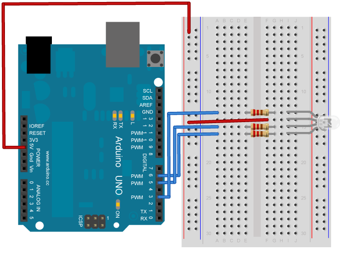
You’ll need five wires to make the circuit above. Connect a red wire to one of the long vertical rows on your breadboard. Connect the other end to the 5V pin on your Arduino.
Place an RGB LED on your breadboard. Check the datasheet for your specific LED to verify the pins. Connect the power rail you just created to the common anode on the LED.
With your remaining wires, connect your red cathode to pin 3, green cathode to pin 5, and blue cathode to pin 6 in series with the resistors.
RGB LEDs with a common anode share a common power pin. Instead of turning a pin HIGH to illuminate the LED, you need to turn the pin LOW, to create a voltage difference across the diode. So sending 255 via analogWrite() turns the LED off, while a value of 0 turns it on at full brightness. In the code below, you’ll use a little bit of math on the Arduino side, so you can send values which correspond to the expected brightness. Essentially, instead of using analogWrite(pin, brightness), you’ll be calling analogWrite(pin, 255-brightness).
Code
You’ll first set up some global variables for the pins your LED will connect to. This will make it easier to differentiate which one is red, green, and blue in the main part of your program:
const int redPin = 3;
const int greenPin = 5;
const int bluePin = 6;
In your setup(), begin serial communication at 9600 bits of data per second between Arduino and your computer with the line:
Serial.begin(9600);
Also in the setup, you’ll want to configure the pins as outputs:
pinMode(redPin, OUTPUT);\\ pinMode(greenPin, OUTPUT);
pinMode(bluePin, OUTPUT);
Hardware Required
- Arduino Board
- Breadboard
- Hookup wire
- Common anode RGB LED
- Three 220-ohm resistors
For more detail: Read ASCII String using Arduino
- How does the code determine the LED color?
The code parses integers separated by non-alphanumeric characters like commas and uses them to set the color. - Can I use characters other than commas to separate values?
Yes, spaces or periods can also be used to indicate different pieces of information. - Why is the math 255-brightness used in the code?
A common anode LED turns on when a pin is LOW, so the code subtracts the input brightness from 255 to invert the signal. - What serial communication speed is configured?
The setup initializes serial communication at 9600 bits per second. - Which pins are connected to the red, green, and blue cathodes?
The red cathode connects to pin 3, green to pin 5, and blue to pin 6. - How do you connect the common anode of the LED?
The common anode is connected to the power rail created by connecting a wire to the 5V pin. - What happens if you send the value 255 via analogWrite?
Sending 255 turns the LED off because it corresponds to a HIGH state for a common anode configuration. - What is the purpose of the three 220-ohm resistors?
The resistors are placed in series with the red, green, and blue cathodes to limit current.