Hi, today I’ll explain how to make your own little Weather based Music generator.
It’s based on an ESP8266, which is kind of like an Arduino, and it responds to temperature, rain and light intensity.
Don’t expect it to make entire songs or chord progressions. It’s more like Generative Music people sometimes make with Modular Synthesizers. But it’s a little less random then that, it does stick to certain Scales for instance.
Supplies:
ESP8266 (I’m using the Feather Huzzah ESP8266 from Adafruit)
BME280 Temperature, Humidity and Barometric Pressure Sensor (The I2C Version)
Arduino Rain Sensor
25K LDR (Light Dependent Resistor)
Some Resistors (two 47, one 100, one 220 and one 1k Ohm)
Female Midi Connector (5 Pin Din) suitable for PCB mounting
Jumper Wires
Breadboard or some sort of Prototyping board
Computer, I’ll be using one running Windows 8.1, but it should work on any OS as far as I know.
Optional: 1250 mAh LiPo battery with JST connector from Adafruit (only compatible with some ESP’s)
Step 1: Step 1: Software
First of all you need the Arduino IDE.
Then you need the SiLabs CP2104 driver and the ESP8266 Board Package.
This allows your computer to program the ESP via the built in UART and allows the Arduino IDE to program the ESP.
You’ll also need the Arduino Midi Library to be able to send Midi data. It can be done without, but this just makes everything a lot easier.
To communicate with the BME280 I used this BME280-I2C-ESP32 library. (This is for the I2C version of the BME280)
And that library in turn requires Adafruit Unified Sensor Driver. This is not the first time I’ve needed this library in order to use a different library without issues, so I always have this Library bookmarked somewhere.
Step 2: Hardware

Al right so we finally get to the good stuff, the hardware.
As mentioned I used this Adafruit ESP, but it should just work fine with a NodeMCU. I recommend the V2 version as I believe it fits a lot better on a breadboard and you can get them very cheap from eBay or AliExpress. I do like the fact that the Adafruit ESP has a faster CPU, comes with a female JST connector for a LiPo and a charge circuit. It’s also a bit easier to figure out what Pin you’re using. I believe on a NodeMCU the pin Labeled D1 is actually GPIO5 for instance, so you always need a Pinout chart handy. Not a big issue at all, but just convenient for newbies they labeled the Adafruit one so clearly.
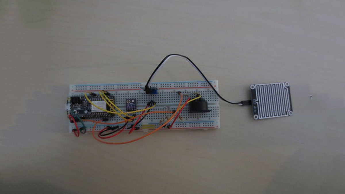
First off let’s connect the BME280, because there are some variations in this model. As you can see from the pictures mine has the one big hole, but there are also some with 2 holes. You can see it has 4 In and Outputs, 1 for power, one for ground and a SCL and SDA. This means it communicates via I2C. I believe other models communicate via SPI. And in some you can chose either SPI or I2C. SPI might require a different Library or at least different code and different wiring. I also believe the S in SPI stands for Serial and I can’t say if this will interfere with the Midi part of this project as that’s also working via Serial connection.
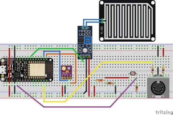
Hooking up this BME is pretty straight forward. On the ESP8266 you can see pin 4 and 5 being labeled SDA and SCL respectively. Just connect those pins directly to the SDA and SCL pin on the BME. Of course also connect VIN to the Positive Rail of the Breadboard and GND to the Negative Rail. Those are in turn connected to the 3V3 and GND pin of the ESP.
Up next we will connect the LDR. In the Fritzing example you can see the 3.3 volts going through a resistor, then it’s split to the LDR and another resistor. Then after the LDR it’s split again to a resistor and to the ADC.
This is to protect the ESP from getting too high voltages and to make sure it’s getting readable values. The ADC can handle 0-1 Volts but the 3V3 delivers 3.3 volts. It probably won’t blow anything up if you go above 1 volt, but it’s not going to work well.
So first we use a Voltage Divider using 220 and 100 ohm resistors to bring down the voltage from 3.3 to 1.031 volts. Then the 25k ohm LDR and the 1k ohm resistor form another Voltage Devider that bring the voltage down from anywhere between 1.031 and 0 volts depending on the amount of light the LDR gets.
Then we have the Rain Sensor. One part says FC-37, the other part says HW-103. I just bought the first one I found on Ebay that said it can handle 3.3 ánd 5 volts. (I think they all can).
This is pretty straight forward, we could use an Analog output, but we can just turn the tiny Trimpot to make the sensor be as sensitive as we want (and we already used our one Analog pin on the ESP). As with the other sensors we have to supply Power from the Positive Rail and connect it to the Ground rail. Sometimes the order of the pins varies though. On mine it’s VCC, Ground, Digital, Analog, but on the Fritzing picture it’s different. But if you just pay attention this should be easy to get right.
And finally, the Midi Jack. On my Breadboard it can’t sit on the edge of the breadboard, as the pins don’t all align. If this bothers you I would try to get a breadboard in a physical store. Or inspect the pictures very well.
As you can see from the schematic, the positive voltage and the Serial signal both go through a 47 ohm resistor.
If you do this project with an Arduino Uno for instance make sure to use 220 ohm resistors!! These ESP’s work on 3.3 V logic, but most Arduino’s use 5.0 V so you have to limit the current that goes through the Midi cable more.
And finally connect the middle pin to the Ground rail. The other 2 pins from the 5 Pin Din aren’t used.
Step 3: Code
And finally we have the code!
In this Zip file I put 2 sketches. ‘LightRainTemp’ just simply tests all the sensors and send back their values.
(Make sure to open the Terminal Window!)
And of course we have the LRTGenerativeMidi (LRT stands for Light, Rain, Temperature) sketch.
Inside you can find a bunch of explanation in comments on what’s going on. I’m not going to go in to how I wrote the whole thing, that would take hours. If you want to know where to get started with something like this I have some other projects in mind. A small Random Riff generator with a few buttons and a Sequencer with a bunch of features I can’t find on other models.
But those I will have to finish designing and coding first. Let me know if you want to be kept up to date about other projects. I haven’t decided if I will make more instructables or make a video series.
Step 4: Hook It Up and Test It!
And now it’s time to test it!
Simply connect a Midi cable, make sure to set your Synth/Keyboard to respond to channel 1 or change the channel in the Arduino code and see if it works!
I’m really curious to see and hear what you do with it. If you make changes, upgrades, tweaks (like to the Light sensor and Temperature values. Outside it might work better or worse then inside) anything.
I’m also curious to see if it works well with all Synthesizers. On my Volca Bass it works perfectly, but on my Neutron the LFO gets stuck as soon as I send a Midi Note. It’s fine when I reboot it, but it’s odd. I’m not sure if there’s something in the Midi Library or in my code, I might try to do it without a Library soon and see if it gets any better.
Thanks for reading and watching and good luck!!
Read more: Weather Based Music Generator (ESP8266 Based Midi Generator)
