In this tutorial you will learn how to make your own 4 ft by 4 ft, Arduino controlled, 3 watt laser engraver / cutter (for thin materials) for around 300$. The main thing that separates this tutorial from other laser engraver tutorials on here is the roughly 42 x 42 inch cutting/engraving area. This project arose when I was trying to create a 20 x 15 pixel coffee table. I needed to be able to cut my own fairly large foam grids in order to make the light separation to create the “pixels”. One of the most expensive parts to creating your own pixel table or wall is creating the grid, most have theirs laser cut out of foam by some sort of online laser cutting service. The only problem with the online service is that it isn’t cheap, and I’m a broke college student. The only alternative I saw was building my own laser cutter.
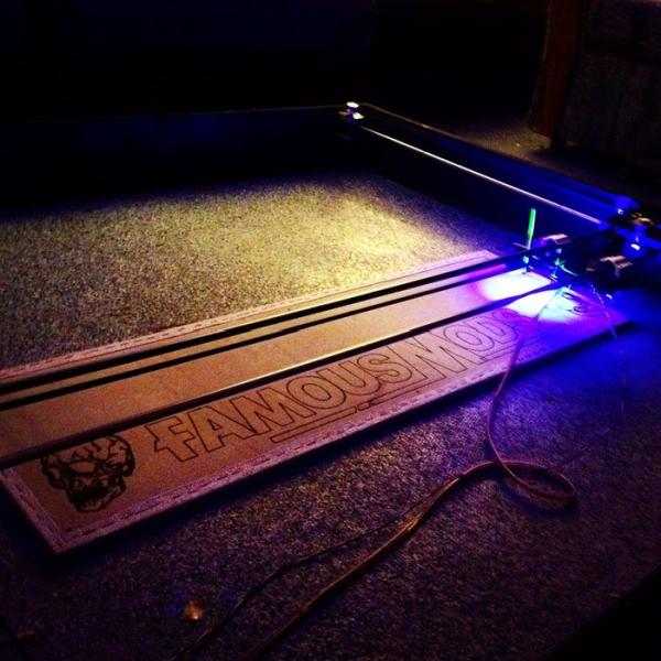
This particular laser cutter is rated for a maximum of 3 watts, even though that power is nothing compared to industrial Co2 laser cutter, which typically starts at around 40 Watts to 500+ watts, the 3 watts is more than enough power to cut thin materials such as foam board, balsa wood, plastic, and cardboard. Even though 3 watts may not be enough to cut through your thicker materials, its more than enough to engrave images on almost any surface (shown in the pictures above).
Step 1: The Materials
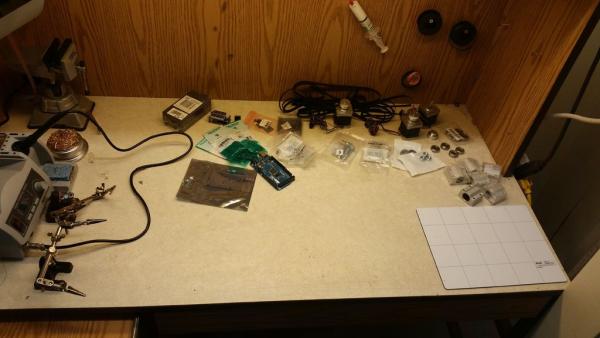
In total your materials (depending on where you buy them from) should come to about $300. Attached is the full bill of materials (B.O.M. V1) for all of the materials I used, including links to each. Remember you do not have to use these exact materials, there are lots of different components that will also work for this build. This B.O.M. does not include the price for bolts, screws, and wood.
Materials
- Arduino R3
- Proto Board
- Stepper Motors
- 3W Laser
- Laser Heat sink
- Power Supply
- DC-DC regulator
- Logic Level MOSFET
- Stepper Motor Driver
- Limit Switches
- Project Box (Something large enough to contain everything in this list)
- Timing Belts
- 10mm Linear Ball Bearing
- Timing Pulley
- Ball Bearings
Not included in B.O.M.
- 2 – 53″x 4″ x 3/4″ Sheets of wood
- 2 – 49.5″ x 4″ x 3/4″ Sheets of woods
- 4 – 3/8″ Steel Round rod
- Various bolts and nuts
- Screws 1.5″
- Liquid Grease white Lithium
- zip-ties
Tools
- Computer
- Circular Saw
- Screw Driver
- Various Drill Bits
- Steel fine grit sandpaper
- Vice (optional)
Step 2: The Circuit
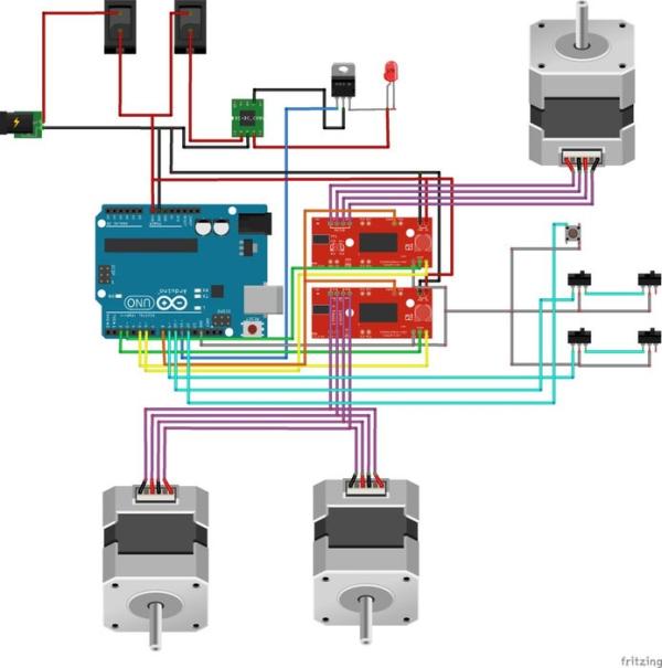
The circuit is pretty straight forward if you follow the diagram posted above. There are however a few technical details you do need to pay close attention too:
- The Stepper Motors: You may notice that two of the stepper motors are run from one driver. After trial and error (and suggestions from other builds) you do need in fact need two stepper motors for one of the axis’s (two stepper motors from one driver). This is so one side of the axis does not lag behind the other. The two combined stepper motors are wired the exact same with one of the two stepper motors coils reversed. This is so that one stepper motor runs in revers to the other, causing them both to pull the belt in the same direction.
- Laser Power: When adjusting the DC-DC step down supply make sure you DO NOT exceed the specs for your laser, this will fry your laser and you will have to purchase another. The laser I am using is rated for 5V and up to roughly 2.4A. Therefore I have the current limited to 2A and the voltage just below 5V.
- Logic Level MOSFET: The MOSFET in this circuit is very crucial, It turns the power to the laser diode itself on and off. A Logic Level MOSFET turns fully on or fully off when very low current is applied to the gate, this is perfect for controlling it with an Arduino because the Arduino sends a very low current to the MOSFET. If you tried to use a standard MOSFET or transistor the laser would not get full power because the Arduino does not supply enough current to fully close the connection between your laser and its ground. In the circuit above the MOSFET is inserted between the laser and ground on the DC-DC step down supply.
- Cooling: One big problem I ran into when I first put this together was the laser diode overheating if I ran it for too long. The heat-sink is NOT sufficient to disperse all the heat from the laser, to fix this issue I added a small computer fan mounted right next to the laser. After this addition I haven’t had any problems with heat even when running it for 9+ hours straight. I also added a fan next to the stepper motor drivers because they also produce a lot of heat even when the laser cutter not running, if the power is on these guys will get very hot.
Step 3: The Assembly
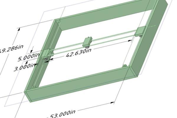
Attached I have included a 3D design for the laser cutter in order to show you the general frame for the project (created in DesignSpark Mechanical). The design is to scale and shows you how to assemble the laser cutter.
- Building the shuttles: This includes the shuttle that holds the laser (the Y axis in this example), and the two shuttles that make the X axis. No Z axis is required, instead of a Z axis (like a 3D printer) the laser will be turned on and off. In the CAD pictures above I’ve given you all the dimensions you should need to be able to assemble the three shuttles, if you have any questions on the dimensions please refer to the attached 3D Design. All the holes drilled for the round rod to fit into the side boards or shuttles are 1/2 inch deep. Make sure you pre-drill all the holes in the shuttles to prevent risk of the board cracking.
- The Round Rod: I purchased 3/8″ steel (Aluminum would work better but steel is cheaper and easier to find) rod from Homedepot, the reason I went with the thicker 3/8″ was to prevent and sagging on the rail. The rod came coated in a grease like substance, this needs to be removed before you can use the rod. Steel sanding pads, steel wool or high grit sand paper should work, after sanding the steel it should be very smooth and look like it does in the pictures above. After everything is assembled the rails need to be coated with white lithium grease, this prevents rusting and helps the shuttles glide.
- The Belt & Stepper Motors: When it came to mounting the stepper motors to the base and attaching the timing belt I used what tools I had at hand. The stepper motors and bearings should go on first before you worry about putting the belt on. In order to mount the motors to the wood I cut a rectangular piece of sheet metal the width of the motors and about twice the width for the length. I then drilled 6 holes, 4 for the top of the motor so you can screw the sheet metal to the stepper motor, and 2 holes on the far side of the sheet metal. I then bent the sheet metal 90 degrees and screwed the sheet metal to the wood. On the opposite side from the stepper motor is where you mount your bearings. Each pulley/bearing set consists of one bolt, 2 bearings, a washer, and sheet metal. I simply drilled two holes in opposite ends of the rectangular piece of sheet metal and one smaller hole in the middle. Then bent the sheet metal into a “C” shape, put the washer on the bolt first followed by the two bearings and finally put the bolt through both holes on the ends of the sheet metal and tightened it down with a nut on the bottom. The sheet metal then gets screwed to the wood using the hole drilled in the center of the sheet metal. As for the timing belt I put a screw through each end of the belt and then screwed each end of the belt to a small piece of wood attached to the corresponding shuttle. You can get a much better picture of what i’m describing in the pictures above.
Read more: 3W 4’x4′ Arduino Laser Cutter/Engraver