
Summary of Arduino Knight Rider Code
Arduino Knight Rider light effect creates a chasing LED sequence using five red LEDs connected to Arduino digital pins 12–8. Each LED anode uses a 330Ω resistor, cathodes share ground, and the sketch turns LEDs on in order from pin 12 down to 8 and back to 12 with 80 ms delays. The project mimics a Knight Rider scanning light and can be simplified using arrays.
Parts used in the Arduino Knight Rider light effect:
- 5x 5mm red LED
- 1x Arduino
- 5x 330Ω resistor
- Jumper wire
Arduino Knight Rider light effect, a simple variation of blink code.
Parts List;
1) 5x 5mm red LED
2) 1x Arduino
3) 5x 330Ω resistor
4) Jumper wire

Instruction;
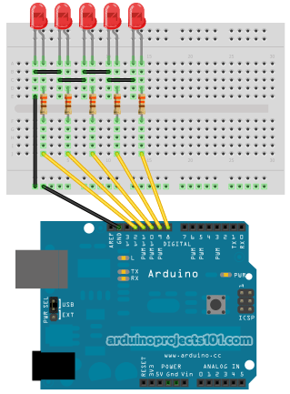
1) Connect all LED as diagram below, make sure cathode lead of LED at ground wire.
2) Connect all 330Ω resistor to anode lead of LED.
3) Connect all jumper wire to digital pin 12, 11, 10, 9 and 8.
Upload this code to your arduino
/*
  Knight Rider
  Create LED chasing effect as knight rider light.

  Coded by: arduinoprojects101.com
 */

void setup() {
  // initialize the digital pin 12, 11, 10, 9, 8 as an output.
  pinMode(12, OUTPUT);
  pinMode(11, OUTPUT);
  pinMode(10, OUTPUT);
  pinMode(9, OUTPUT);
  pinMode(8, OUTPUT);
}

void loop() {
  digitalWrite(12, HIGH);
  delay(80);
  digitalWrite(12, LOW);
  digitalWrite(11, HIGH);
  delay(80);
  digitalWrite(11, LOW);
  digitalWrite(10, HIGH);
  delay(80);
  digitalWrite(10, LOW);
  digitalWrite(9, HIGH);
  delay(80);
  digitalWrite(9, LOW);
  digitalWrite(8, HIGH);
  delay(80);
  digitalWrite(8, LOW);
  // reverse
  digitalWrite(8, HIGH);
  delay(80);
  digitalWrite(8, LOW);
  digitalWrite(9, HIGH);
  delay(80);
  digitalWrite(9, LOW);
  digitalWrite(10, HIGH);
  delay(80);
  digitalWrite(10, LOW);
  digitalWrite(11, HIGH);
  delay(80);
  digitalWrite(11, LOW);
  digitalWrite(12, HIGH);
  delay(80);
  digitalWrite(12, LOW);
}
Essentially, this arduino project is similar to the blink project, as it turns on the LED lights in sequence from LED 12 to LED 8, before returning the sequence back to LED 12. The knight rider light code is simply a coded sequence of blinking for easier comprehension. This code can be made simpler using array code. Enjoy yourself!
Source: Arduino Knight Rider Code
- How are the LEDs connected in this project?
Each LED cathode is connected to ground and each anode is connected through a 330Ω resistor to an Arduino digital pin (12, 11, 10, 9, 8). - Which Arduino pins are used for the LEDs?
The LEDs are connected to digital pins 12, 11, 10, 9, and 8. - What resistor value is used for each LED?
Each LED uses a 330Ω resistor on its anode. - What does the supplied code do?
The code lights each LED in sequence from pin 12 to pin 8 with 80 ms delays, then reverses the sequence back to pin 12, creating a chasing effect. - How long is the delay between LED changes?
The code uses an 80 millisecond delay between turning LEDs on and off. - Can the code be simplified?
The article states the code can be made simpler using array code. - Do the LEDs share a common ground?
Yes, the LED cathodes are connected to the ground wire. - Is this project similar to the Arduino blink example?
Yes, it is similar to the blink project but uses a sequence of multiple LEDs to create a Knight Rider effect.
