
Summary of esp32 devkit v1 pinout
The article details the GPIO capabilities of the ESP32 DEVKIT, describing available pins (36 on the dev board), digital input-only pins, ADC (18 channels, 12-bit), DACs, capacitive touch sensors, memory card interface pins, external interrupts, PWM and motor-control features, I2C pins, RTC-capable pins, and the built-in hall sensor. It maps many peripheral functions to specific GPIO numbers and notes limitations (e.g., pins 34–39 are input-only, ADC nonlinearity).
Parts used in theESP32 DEVKIT:
- ESP32 DEVKIT development board (ESP-WROOM-32 module)
- Onboard GPIO pins (36 board pins, 34 usable GPIOs)
- Analog to Digital Converters (ADC1 and ADC2 channels)
- Digital to Analog Converters (DAC_1 GPIO25, DAC_2 GPIO26)
- Capacitive touch sensors (TOUCH0–TOUCH9 mapped to GPIOs)
- I2C pins (GPIO21 SDA, GPIO22 SCL)
- RTC-capable GPIO pins
- Onboard hall effect sensor
- Memory card interface pins (HS2 signals mapped to GPIOs)
- PWM and motor-control related registers and channels
GPIO pins of ESP32 DEVKIT
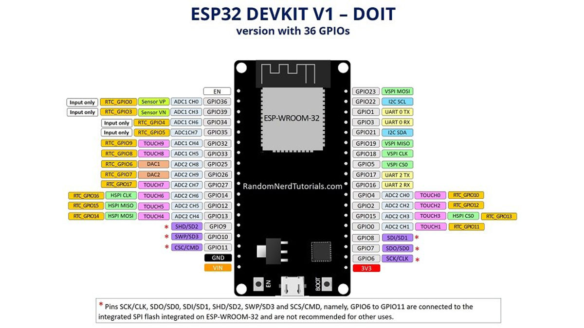
As previously stated, the chip on this board contains 48 GPIO pins, although not all pins are reachable via dev boards. The ESP32 devkit features a total of 36 pins, with 18 pins located on each side of the board, as illustrated in the image provided. There are 34 GPIO pins with various functionalities that can be set using specific registers. Various GPIOs, such as digital input, digital output, analog input, and analog output, as well as capacitive touch and UART communication, are among the numerous features mentioned.
digital input GPIO pins
It comes with six GPIO pins specifically meant for digital input. Setting them up as digital output pins is not feasible. They do not have push-pull resistors that are integrated. They can only be used as digital input pins.
Interface GPIO has a pin at number 34.
GPIO interface’s Pin 35.
GPIO interface pin 36.
The thirty-seventh pin on a General Purpose Input/Output (GPIO) interface.
GPIO pin number 38.
Set GPIO pin to 39
Check this tutorial: How to use push button with ESP32
Analog to digital converter or Analog GPIO pins
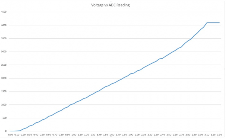
This board has the ability to accommodate 18 ADC channels. Each channel has a 12-bit capacity. Therefore, it possesses a high-quality resolution. It is capable of measuring analog voltage, current, and any analog sensor that outputs in analog voltage. These ADCs are capable of being utilized while in sleep mode to decrease power usage. The resolution of each ADC channel is 12 bits, which is equivalent to
3.3 volt is the reference voltage and 4095 represents the smallest step of the ADC.
Therefore, the smallest voltage detectable by these ADC channels is approximately 80 microvolts. Any result below this will be considered a mistake. In future tutorials, I will go into more detail about it. The main limitation of the ESP32 ADC is its non-linear performance. Please refer to the diagram for more details.
- Below is the display of the correlation between Analog pins and GPIO pins.
Below is the display of the correlation between Analog pins and GPIO pins.
ADC1 channel 0 is connected to pin GPIO36.
ADC1 channel 1 corresponds to GPIO pin 37.
ADC1 channel 2 corresponds to GPIO pin number 38.
ADC1 Channel 3 is connected to GPIO39.
ADC1 channel 4 corresponds to GPIO pin 32.
ADC1 channel 5 corresponds to GPIO pin 33.
ADC1_CH6 is equivalent to GPIO34.
ADC1 channel 7 corresponds to GPIO pin 35.
ADC2 channel 0 corresponds to GPIO4.
ADC2 channel 1 is connected to GPIO pin 0.
ADC2 channel 2 is connected to GPIO2.
Analog Digital Converter Channel 2 Channel 3 is connected to General Purpose Input Output pin 15.
ADC2 channel 4 corresponds to the GPIO pin 13.
ADC2 channel 5 corresponds to GPIO pin 12.
ADC2 Channel 6 corresponds to GPIO pin 14.
ADC channel 7 corresponds to GPIO pin 27.
ADC2_CH8 corresponds to GPIO25.
ADC2 Channel 9 corresponds to GPIO pin 26.
Check this tutorial : How to use ADC of ESP32
Digital to analog converter pins
The development board has onboard two 8-bit digital to analog converter incorporated on the board to convert digital signal into analog signal. DACs in their function have the aim of converting numeric code values into suitable voltage or current levels. Some of the uses are in voltage control, pulse width modulation control and many others. Since this board has two embedded DACs, it can provide two analog signals at the same time Therefore, it can measure or stimulate real systems by controlling analog signals.
- DAC_1 is equivalent to GPIO25.
- DAC_2 is equivalent to GPIO26.
Touch sensor pins of Devkit
There are 10 capacitive touch sensors integrated in ESP-WROOM-32. By using this development board, you can eliminate the need for using separate touch sensors in your project. These capacitive touch sensors can recognize different electrical and magnetic waves, including the ability to detect magnetic fields. These touch sensors enable the use of a condensed set of pads instead of physical push buttons.
- TOUCH0 is equal to GPIO4.
- TOUCH1 is equivalent to GPIO0.
- Contact2 – GPIO2
- There is a connection between TOUCH3 and GPIO15.
- TOUCH4 is equivalent to GPIO13.
- Touch5 and GPIO12 are the same.
- TOUCH6 is equivalent to GPIO14.
- TOUCH7 is equivalent to GPIO27.
- TOUCH8 is equivalent to GPIO33.
- TOUCH9 is equivalent to GPIO32.
How to use touch pins and how to use touch pins as a digital button?
Memory card interfacing pins
Support for interfacing with memory cards through these pins is also available.
Support for interfacing with memory cards through these pins is also available.
- HS2_CLK and MTMS are interchangeable.
HS2 command – Output change.
HS2_DATA0 is the same as GPIO2.
GPIO4 is linked with HS2_DATA1.
HS2_DATA2 – MTDI – HS2 data 2 – MTDI
HS2_DATA3 – MTCK stands for High Speed 2 Data 3 – Maintenance Check.
External interrupt pins
External interrupts can be triggered using any of the general purpose input output pins. External interrupts provide significant benefits. Instead of constantly checking the status of a pin, you can use it as an interrupt to track changes.
PWM GPIO pins
PWM can be produced on any GPIO pins except for digital input pins 34 to 39. Because these pins cannot be used as digital output pins. PWM signals are signals that are produced digitally. PWM pins can reach a maximum frequency of 80 MHz. By following these instructions, you have the ability to assign a different pin as a PWM pin.
- Select a particular frequency for pulse width modulation.
- Select either the duty cycle or pulse duration.
- Select the PWM channel. ESP32 provides a grand total of 16 PWM channels available for utilization.
- Assign a digital pin for selecting the PWM channel.
PWM motor control feature
The internal registers of the ESP32 chip are also utilized to support motor control functionality. To make use of this functionality, just configure these registers with the GPIO pins you want. More information about these registers is available in the datasheet. Here are the names of the registers.
- PWM1_OUT linked to input pins IN0~2.
- Input signals for the initial three fault inputs of PWM channel 0.
- PWM1_FLT_IN0 converted to 2.
- Record input signals on channels 0 through 2 of PWM0.
- Capture inputs 0 to 2 using PWM1.
- Synchronize Input 0 to 2 with Pulse Width Modulation 0.
- Synchronize PWM1_SYNC_IN0 with 2.
I2C communication pins
There are designated pins for two-wire I2C communication. One pin facilitates data transfer, while another pin aids in clock synchronization.
- GPIO21 is the pin named SDA.
- GPIO22 is the SCL pin.
Published is an article on how to interface an I2C LCD with ESP32. This article expounds on how to use I2C pins in detail to ensure that users can implement it in their devices. For further details, I would encourage you to go through the whole article.
RTC pins of ESP32 devKit
This board also includes RTC pins that can be utilized to wake up the ESP32 from sleep mode.
- RTC_GPIO0 to GPIO36.
- RTC_GPIO3 is also known as GPIO39.
- RTC_GPIO4 corresponds to pin number GPIO34.
- RTC_GPIO5 is also known as GPIO35.
- RTC_GPIO6 is equivalent to GPIO25.
- RTC_GPIO7 corresponds to GPIO26.
- RTC_GPIO8 is equal to GPIO33.
- RTC_GPIO9 is equivalent to GPIO32.
- RTC_GPIO10 is equivalent to GPIO4.
- RTC_GPIO11 is equivalent to GPIO0.
- RTC_GPIO12 is equivalent to GPIO2.
- RTC_GPIO13 through GPIO15
- RTC_GPIO14 is equivalent to GPIO13.
- RTC_GPIO15 corresponds to GPIO12.
- RTC_GPIO16 is equivalent to GPIO14.
- RTC_GPIO17 to GPIO27 – RTC_GPIO17 until GPIO27.
Hall sensor pin
- A complete guide on How to use built-in hall effect sensor of ESP32
It is equipped with a single hall sensor that is utilized for detecting the magnetic field. When you place this development board in a magnetic field, ESP32 produces a slight voltage that can be detected by any pin. I will publish a tutorial in future posts. The above image displays additional characteristics of the ESP32 development board and its pins.
- How many pins does the ESP32 DEVKIT board have?
The ESP32 DEVKIT features 36 board pins with 18 pins on each side and exposes 34 GPIO pins. - Which GPIO pins are digital input only?
GPIO pins 34, 35, 36, 37, 38, and 39 are digital input only and cannot be used as digital outputs. - How many ADC channels does the board support and what is their resolution?
The board supports 18 ADC channels with 12-bit resolution (0–4095) and 3.3 V reference. - Which pins correspond to the onboard DACs?
DAC_1 is GPIO25 and DAC_2 is GPIO26. - How many capacitive touch sensors are available and where are they mapped?
There are 10 touch sensors TOUCH0–TOUCH9 mapped to GPIO4, GPIO0, GPIO2, GPIO15, GPIO13, GPIO12, GPIO14, GPIO27, GPIO33, and GPIO32 respectively. - Which pins are used for I2C communication?
GPIO21 is SDA and GPIO22 is SCL for I2C communication. - Can any GPIO be used for external interrupts?
Yes, external interrupts can be triggered using any of the general purpose GPIO pins. - Which GPIOs cannot be used for PWM?
Digital input-only pins 34 to 39 cannot be used as PWM outputs. - Does the board include RTC-capable pins for wake-up?
Yes, the board includes many RTC-capable pins such as RTC_GPIO0 to RTC_GPIO17 mapped to various GPIOs listed in the article. - Is there a built-in sensor for detecting magnetic fields?
Yes, the ESP32 has a built-in hall effect sensor for detecting magnetic fields.