
Summary of DIY Binary Clock with Arduino
Yesterday my friend Pedro and I built a working Arduino binary clock. We wired 13 LEDs (each with a 220Ω resistor) to Arduino digital pins 1–13, used two push-buttons on analog inputs A0 and A5 to adjust hours/minutes, and a normal button on digital pin 0 to toggle LEDs. Buttons use 2.2KΩ pull-up resistors tied to 5V and ground. The larger LED leg goes to the Arduino output; the other leg goes to ground. The project runs on a breadboard with connecting wires.
Parts used in the Binary Clock:
- Arduino
- 13x LEDs (color of your choice)
- 13x 220 Ohms resistors
- 3x 2.2 K Ohms resistors
- 2x push-buttons
- 1x normal button
- Breadboard
- Wires
Yesterday I was going to start watching a movie, when me and my friend pedro decided to give up on the movie and build a binary clock. After sometime thinking on how to program it, we made it. It works beautifully, so I decided to show here how I’ve done. It may not be the easiest way to make it work, but that’s what we’ve done.

Parts:
– Arduino
– 13x Leds (You choose the color)
– 13x 220Ohms Resistors
– 3x 2.2KOhms Resistos
– 2x Push-Buttons
– 1x Normal Button
– Bread Board
– Wire
Well, this is a quite simple circuit, but can be tricky for some people, so I will try to explain how it work and how to assemble.
How it works
I think with this images you can understand how it will work. The leds which are on, you just need to sum the numbers, and it will give current time.
Assembling
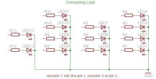
To assemble the circuit, you will need to connect first the resistors and leds. To do it, just hook up leds + resistor from the pin 1 to 13. Remember that the bigger leg of the led is positive, and need to be connected to arduino output pin, and the other leg should be on the ground.
So that the code will work for the circuit, you should use the leds like this, LED 1 to PIN 1, LED 2 to PIN 2, and so on…
For connecting the buttons, I’ve used one digital input and two analog inputs. To set change the hour/minute, you will need to use two push-buttons. And they need to be connected to the analog input pin 0 and 5. And to turn leds ON/OFF I’ve used a normal button that is connected to digital input pin 0. To make it work, you need use one leg of the buttons on a 2.2K Ohm resistor connected to the 5V output together with the analog/digital input, and the other leg going to the ground, something like this:
– 13x Leds (You choose the color)
– 13x 220Ohms Resistors
For more detail: DIY Binary Clock with Arduino
- How many LEDs are used in the project?
The project uses 13 LEDs. - Which Arduino pins are the LEDs connected to?
The LEDs are connected to Arduino pins 1 through 13 respectively. - What resistor values are required for the LEDs and buttons?
The LEDs use 220 Ohm resistors and the buttons use 2.2 K Ohm resistors. - Which pins are the hour and minute adjustment buttons connected to?
The two push-buttons for changing hour and minute are connected to analog input pins A0 and A5. - Where is the ON/OFF button connected?
The normal button to turn LEDs on or off is connected to digital input pin 0. - How should the LED legs be oriented?
The longer leg of the LED is positive and should be connected to the Arduino output pin; the other leg goes to ground. - How are the button resistors wired?
One leg of each button is on a 2.2 K Ohm resistor connected to 5V together with the input pin, and the other leg goes to ground. - Do the LEDs represent time directly?
Yes, LEDs that are on correspond to binary values you sum to get the current time.