
Summary of How to Build an Arduino Voice Controlled TV Remote
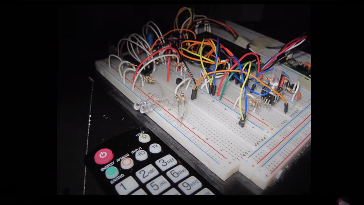
This article details an Arduino-based voice-controlled TV remote project. It utilizes an Arduino board, a 16x2 LCD for display, a voice recognition module via SoftwareSerial, IR LEDs for signal transmission, and push buttons for menu navigation. The system stores command data in EEPROM and uses interrupt pins to track rotary encoder pulses for menu selection.
Parts used in the Voice Controlled TV Remote:
- Arduino Board
- 16x2 LCD Display
- Voice Recognition Module
- Infrared (IR) LEDs
- Push Button
- Rotary Encoder (implied by pulse counting)
- EEPROM Memory
- Wires and Breadboard
#include <EEPROM.h>
#include <Wire.h>
#include <SoftwareSerial.h>
#include <LiquidCrystal.h>
SoftwareSerial voice = SoftwareSerial(15, 16);
LiquidCrystal lcd(5, 6, 7, 8, 9, 10);
int pulses, A_SIG=0, B_SIG=1, menu=0, datacount, i, buttoncount=0;
int count, j, k, m, ready=0, even=0, fail, first_but=0, second_but=0;
word Power[100];
word Remote[100];
//word Remote2[100];
word mute_remote[100];
word enter_remote[100];
byte datlow, dathigh, addlow, addhigh;
long Start, Stop;
char voice_response, voice_response_mem='#', status_in[8];
char upletter[] = "ABCDEFGHIJKLMNOPQRSTUVWXYZ";
long timeout;
void setup(){
attachInterrupt(0, A_RISE, RISING);
attachInterrupt(1, B_RISE, RISING);
pinMode(11, OUTPUT);//IR_Encoder_Interrupt Select
pinMode(12, OUTPUT);//EncoderLED GREEN
pinMode(13, OUTPUT);//EncoderLED RED
pinMode(14, INPUT);//Button Active Low
pinMode(15, INPUT);//TX from Voice
pinMode(16, OUTPUT);//RX to Voice
pinMode(4, OUTPUT);//IR LEDs
digitalWrite(11, LOW);//low-encoder high-IR receiver
Serial.begin(115200);
voice.begin(9600);
Wire.begin();
lcd.begin(16, 2);
buttoncount = EEPROM.read(0);
lcd.print("Voice Remote");
lcd.setCursor(0,1);
lcd.print(buttoncount);
lcd.print(" Commands");
delay(2000);
voice_start();
//voice.print('b');//break
//voice_status();
}//setup
void loop(){
lcd.clear();
if(pulses>=30 && menu==0)
pulses=30;
if(pulses>=60 && menu==1)
pulses=60;
if(pulses<0)
pulses=0;
 if(pulses>=10 && pulses<=20 && menu==0){
lcd.print("Program Mode?");
if(digitalRead(14)==LOW){
delay(500);
lcd.clear();
pulses=0;
menu=1;}
}
if(pulses>=0 && pulses<10 && menu==0){
lcd.print("Listen Mode?");
if(digitalRead(14)==LOW){
delay(500);
pulses=0;
menu=2;}
}
if(pulses>=20 && pulses<=30 && menu==0){
lcd.print("Reboot?");
if(digitalRead(14)==LOW){
delay(500);
voice_start();}
}
if(pulses>=10 && pulses<=20 && menu==0){
lcd.print("Program Mode?");
if(digitalRead(14)==LOW){
delay(500);
lcd.clear();
pulses=0;
menu=1;}
}
if(pulses>=0 && pulses<10 && menu==0){
lcd.print("Listen Mode?");
if(digitalRead(14)==LOW){
delay(500);
pulses=0;
menu=2;}
}
if(pulses>=20 && pulses<=30 && menu==0){
lcd.print("Reboot?");
if(digitalRead(14)==LOW){
delay(500);
voice_start();}
}
For more detail: How to Build an Arduino Voice Controlled TV Remote
-
How does the system initialize?
The setup function initializes serial communication at 115200 baud, voice at 9600 baud, begins the Wire library, starts the LCD, reads button counts from EEPROM, and displays "Voice Remote" with the count. -
What is the purpose of the rotary encoder pulses?
Pulses are used to navigate through different menu options like Program Mode, Listen Mode, and Reboot based on specific thresholds. -
How does the user select a menu option?
The user presses a button connected to pin 14 when the desired option is displayed on the LCD to confirm the selection. -
What happens if the pulse count is between 10 and 20?
The LCD displays "Program Mode?" and pressing the button clears the screen, resets pulses to 0, and sets the menu state to 1. -
How does the system handle the Listen Mode?
If pulses are between 0 and 10, the LCD shows "Listen Mode?", and pressing the button resets pulses and sets the menu state to 2. -
What triggers a reboot in this system?
If pulses are between 20 and 30, the LCD asks "Reboot?", and pressing the button calls the voice_start function to restart the voice process. -
Which pins are configured as outputs for LEDs?
Pins 12 and 13 are set as outputs for Green and Red Encoder LEDs respectively, while pin 4 controls the IR LEDs. -
How are interrupts utilized in the code?
Interrupts are attached to pins 0 and 1 to trigger functions A_RISE and B_RISE on rising edges, likely for tracking encoder movement.
