The smartwalker is being developed for a project called “design for everyone” at Howest university college of Applied Sciences (Belgium). We are a group of design and occupational therapy students. This project is specifically made for an individual person: Peter.
Peter can’t see nor hear. When he goes to the train station he relies on his personal assistant to guide him to the station. This wasn’t a problem for many years however peter is getting older. As a result he uses the shoulder of his assistant as a support. What he needs is a walker. This brings its own problems with it. The connection between this assistant becomes less good. That’s where the smartwalker commes to help. It gives rest to the shoulder of Nancy and Peter more freedom.
The smartwalker is a do-it-yourself assistive technology (DIY-AT) that uses common electronical components like arduino and 3D printing techniques to “hack “a normal walker in to a smart one.
Supplies
The system is divided in 5 core functionalities. The components for these functionalities are listed below.
Visibility
- 1 x traffic red spray paint
- 2 x traffic white spray paint
- 1 x red reflective tape
- 1 x fluo shirt
- 1 x A4 transfer paper for fabrics inktjet printer
- 2 x Red LED
- 2 x White LED
- 1 x daylight sensor
- 3D printer White PLA filament
- Straps
- Sand paper
Communication and detection
- 1 x Arduino uno
- 4 x HCSR-04 distance sensor
- 1 x Arduino case (we did some tinkering and came up with our own design but you can use a standard one.) 2 x Batteries
- 2 x sensor
- 2 x solenoid valve
- 3D printer White PLA
- filament Black PLA filament
- Straps 4 x sensor cover
- 4 x sensor lid
- 2 x feedback cover
- 2 x feedback lid
- scrap wood
Charging
- trickle charger
- plugin timer switch
- correct adapter for batteries
- 2x scooter batteries
- (optional) your own battery system that’s more reliable than ours.
Guidance
- Tube 300 mm, radius 20
- 3D printer Black filament
- Handlebar tape
- Magnets
- Strong glue
Common and essential items
- soldering iron
- 3D printer
- maker tools
- Walker
For a BOM referencing to Belgian and online stores you can use this link:
https://docs.google.com/spreadsheets/d/1mLYQAolRUxFVOxOkVFLsvvLMEJUAZNkMYNYqnwkUgTM/edit?usp=sharing
Step 1: VISIBILITY
There are two main components to make the user more visible. These are a custom made fluo jacket and modifications to the walker.
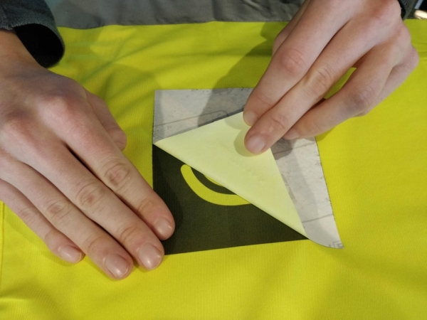
The Fluo jacket
- Use the file “fluo_jacket_logos” to print the labels on fabric transfer paper with an inktjet printer.
- Follow the instructions for your specific transfer paper.
- The text goes on the front the logo’s go on the back.
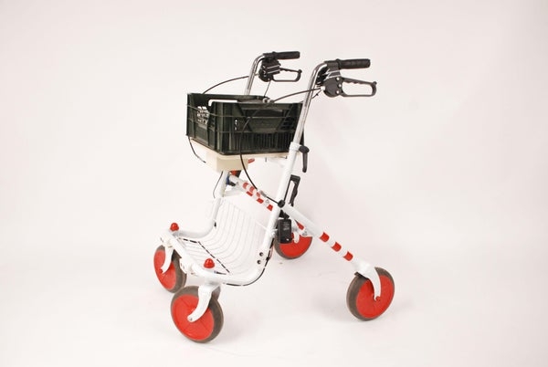
Modifications to the walker
The walker became more visible by adapting elements that are used on white canes that are normally used by blind people. The walker is white with red reflecting accents. These are the steps for painting the walker :
- First consult with your user for the color scheme of the walker.
- secondly remove everything from the walker that doesn’t need paint. these are things like brakes, bolts,…
- lightly sand the tubes and other areas that need painting.
- Spray paint in different layers to get an even coverage. ( to get even better coverage lightly sanding between layers can help). Follow the instructions on the can for more detailed information
- Add extra details with reflective red or white tape.
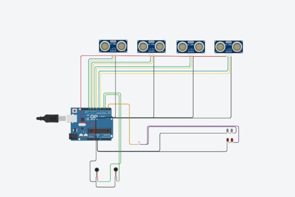
Step 2: CODE and Arduino Circuit
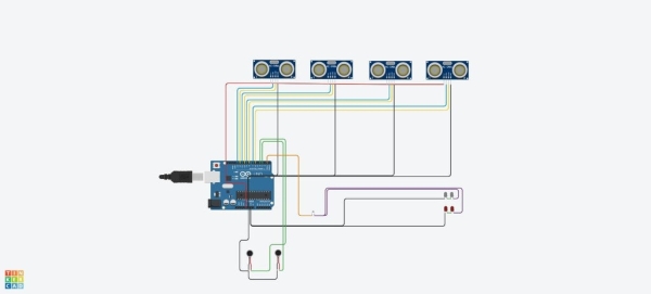
Before doing the things in STEP 3 a good working arduino code is needed. this code can be found here. In the code different distances can be set so different distances give different feedback. To connect the electrical component the following circuit is used (see picture).
It is recommended to test this circuit and code rigorously before mounting it on the walker. It will be more efficient that way. You can do this with a breadboard or other quick electronic prototyping ways like alligator clamps,…
Step 3: COMMUNICATION and DETECTION
The communication and detection system has two levels. We have the level of the electronics and the level of the 3D printed components that are used to connect some of the electronics to the walker. next to this there are some custom made solutions to make the whole system more weatherproof.
The first assembly that is required are the electronics:
- Connect the electronics like the electronic circuit from STEP 3.
- Connect everything together with cables of the appropriate length.
- Do a test fitting by taping the bare electronic components to there right location. One of the pictures shows where the sensors and feedback systems should be located.
- The relays and Arduino are located underneath a basket in a custom made container made from scrap wood. If you decide to do this it is recommended to make this over sized because there will be a lot of extra things you would want to store there like excess wire. The basket was added because our client wants this for his grocery’s.
The second assembly that is required are the 3D printed components to house the electronics:
- Print 4x the following:
- Sensor cover
- Sensor lid
- print 2x:
- Feedback cover
- Feedback lid
- Put the sensors in there appropriate case and connect with two straps to the tubes of the walker. For the right location you can check the pictures.
- Put the feedback system in the right case and connect with two straps at the brakes. You will also need to bolt the cover to the lid as shown in one of the pictures.
Step 4: CHARGING and POWER
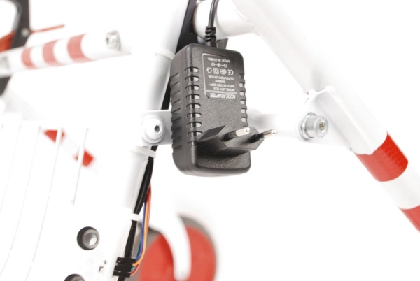
For charging and the whole power system in general we advice you to do some extra tinkering. We now this can be improved easily. We didn’t have the time nor the money to come up with an easy to use plug and play solution. Our solution requires some more steps. We think the processes can be more streamlined.
The power system we now use is based around two very heavy scooter batteries. They are charged with an adapter that is rated for the batteries. However this charger has no stop so it could overcharge the batteries. The solution for this is an electronic plug switch that stops the charging after a certain amount of time.
What we really recommend is a trickle charger that chargers the batteries properly.
And even then the world of batteries is a big one so there are a lot of options.
Step 5: GUIDANCE

The guidance system is essential because a deaf and blind person can’t go walk on his own with the system. The system is a simple tube connected to the walker with strong neodymium magnets. This is because it makes it possible to remove the guidance handle when going to a doorway.
- cut the tube to the right length 300 mm
- print the piece “guidance”.
- Glue the magnets it to the 3D print with a strong glue
- By heating the tube you can fit the 3D print to the tube.
Source: SMARTWALKER D4E1