Summary of Communication Between Two Arduinos Using NRF24L01
Parts used in the Arduino NRF24L01 Communication Project:
- NRF24L01 module
- Cheap Arduino Uno
- Powerbank
- Wires
While building Arduino or any other microcontroller platform project over time the need will arise to establish communication between two of the Arduino boards or microcontrollers for data exchange and/or control. This communication could be achieved using either wired or wireless process. For wireless communication between devices, quite a number of options exist including WiFi, GSM/GPRS, Bluetooth, RF and more recent technologies like LoRaWAN among others. All of these communication protocols have their pros and cons and the situation is in which they are the best fit. For mid-range communication between two microcontrollers, for example, one of the most suitable communication protocol is RF (radio frequency) as it has a good cost to performance ratio and a very good communication range can be attained using certain modules.
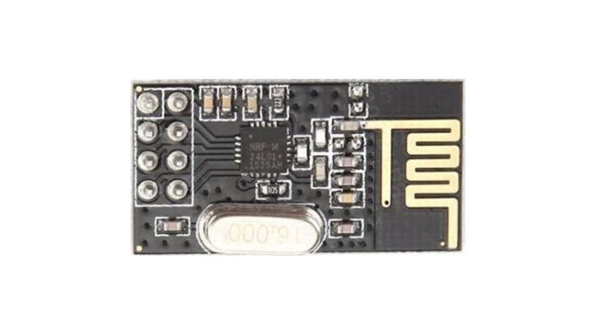
Today, we will look at the radio frequency based communication between microcontrollers using one of the most popular RF communication modules; the NRF24LO1 communication module.
The NRF24L01 module is a low-cost (less than$3) ultra-low power, bi-directional transceiver module. It is designed to operate within the 2.4GHz ISM band which means it can be used for projects with industrial, scientific and medical applications. The module can achieve data rates as high as 2Mbits! and uses a high-speed SPI interface in order to communicate with the Arduino and other kind of microcontroller and development boards.
One of the best features of this module, aside the ease with which it can be used with Arduino and other microcontroller, is its low power consumption. This module consumes, less than 14mA in full communication mode and consumes only a few microamps in power down mode. This makes it ideal for projects with long battery life specifications.
To demonstrate the use of this module with Arduino, we will build a simple transmitter and receiver project. The transmitter sends data at a regular interval to the receiver which displays the received data on the serial monitor. This dummy data being transferred could be data from sensors in a real life application or signals to get the receiver to perform certain actions.
Required Components
The following components are required to build this project;
The exact components used for this tutorial, as usual, can be bought via the links attached to them.
Schematics
The schematics for this project is quite simple, all we need to do is to connect the NRF24L01 to the Arduino. The NRF24l01’s design is not breadboard friendly, so we will have to connect it to the Arduino with jumper wires.
Connect the components as shown in the schematics below.
Read more: Communication Between Two Arduinos Using NRF24L01
- What communication protocol is suitable for mid-range microcontroller projects?
RF (radio frequency) is a suitable protocol due to its good cost to performance ratio and long range. - Can the NRF24L01 be used with industrial applications?
Yes, it operates within the 2.4GHz ISM band which allows use in industrial, scientific, and medical applications. - How fast can the NRF24L01 transmit data?
The module can achieve data rates as high as 2Mbits per second. - Does the NRF24L01 consume a lot of power?
No, it consumes less than 14mA in full communication mode and only a few microamps in power down mode. - What interface does the NRF24L01 use to talk to the Arduino?
It uses a high-speed SPI interface to communicate with the Arduino and other microcontrollers. - Is the NRF24L01 module easy to breadboard?
No, the design is not breadboard friendly so jumper wires must be used to connect it to the Arduino. - What does the transmitter send in this project?
The transmitter sends dummy data at regular intervals which could represent sensor data or control signals. - Where is the received data displayed in this tutorial?
The receiver displays the received data on the serial monitor.