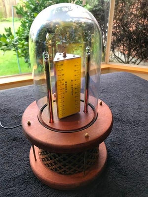
In this post we will learn how to create Nixie-Trilateral-Clock: While waiting for the delivery of parts for another project I decided to push ahead with this project. At its heart is two IN-13M Nixie tubes. These tubes are designed to provide a linear scale between the maximum and minimum points using an illuminated column. The project uses two of these IN-13M, three-wire Nixie tubes to show, time (Hours and Minutes), temperature (Celsius and Fahrenheit), Humidity (percentage), and Pressure (millibars).
At this point, I would like to thank Dr. Scott M. Baker for his great web site, which provided me with all the information I needed to get these Nixie tubes to work. In particular the Current Regulator as displayed and detailed on his web site.
The project uses a BME280 sensor to determine the temperature, pressure and humidity and RTC clock to monitor time. As the system needs to display six different values it was necessary to construct a rotating central display that showed these values against six scales. In order to achieve this an equilateral triangle of wood was fashioned, each side showing two sets of values. A stepper motor was mounted under the top platform and this motor rotates through 120 degrees in time for the next set of values to be displayed on the two Nixie tubes.
NOTE: The IN-13M nixie tube cannot be considered as accurate at displaying a numerical value as saying the IN-14, or any of the other Nixie tubes.
Steps how to make Nixie Trilateral Clock:
Step 1: Equipment
EQUIPMENT
1. Arduino Uno R3
2. 16X2 LCD display (Used for testing only, removed upon final assembly)
3. BME280 sensor
4. RTC Real-time Clock with battery backup
5. 12V – 150V DC-DC boost converter
6. 12V – 5V DC-DC step-down converter
7. 12V 1A – Power Adapter
8. 5V Stepper Motor 28BY-48 and Controller ULN2003
9. Wood for the base, platform, and scale.
10. Glass dome
11. 3mm brass rod
12. 3mm brass dome nuts
13. Brass sheet, 2mm (300mm x 600mm)
14. Black 100gsm paper
15. Various cables
16. Single pole switch
17. 5v red LED
18. 12V positive center adapter inlet
19. Various screws, plastic mounts, heat shrink, PCB pins, wire
20. PCB board (3 X 40mm X 20mm)
21. 5mm red LED
22. Current Regulator:
a. 1K resistor
b. 1uF Capacity
c. 470ohm resistor
d. 220K resistor
e. 2K trim pot, 3296
f. MJE340 NPN transistor
Step 2: CONSTRUCTION
I have attached the original Russian IN-13 datasheet, MJE340 datasheet, TSR-3296 datasheet, MS Publisher Scales format, and Current Regulator schematic
When examining the IN-13 you will notice a pink dot inside the glass at the bottom of the tube. With this on the right-hand side, the wires as read from left to right are Aux-cathode, Ind-cathode, and Anode. It is important that the anode is not overloaded and a maximum of 140v is recommended.
When examining the 2K trim-pot the wiper connection is the center connection and either of the two outside connections can be used. When examining the MJE340 transistor view the black plastic side, not the heat sink side, reading the connections from left to right gives Emitter (E – 1), Collector (C – 2), and Base (B – 3).
When constructing the Current regulator resistors can be installed in either direction, however, the capacitor must be installed with the “minus” grey strip facing the GND. Also, ensure that all GNDs return to a single point, this is most important for the High Voltage GND which must also return to the same point.
The most common mistake is wire the MJE340 the wrong way around.