
Summary of DIY Arduino Relay Driver Shield
This DIY project details the design and construction of a 3-Channel Arduino Relay Shield for controlling AC appliances via home automation. The shield features an isolated PCB with optocouplers, transistors, and screw terminals to safely interface low-voltage Arduino signals with high-voltage loads. Users can fabricate the board using EasyEDA or order it directly from JLCPCB, connecting three relays to specific Arduino pins to operate devices like bulbs.
Parts used in the 3-Channel Arduino Relay Shield:
- SPDT relay 12v
- 817 Optocoupler
- Transistor BC547
- SMD LEDs
- PCB ordered from JLCPCB
- Terminal Block 2 pin
- 1N4007 Diode
- 1k Resistor
- Burg sticks male
- Jumper
- Push Button
- Power supply
- Arduino Uno
- Connecting wire
- AC appliances
In this DIY project we make a 3-Channel Arduino Relay Shield Circuit for relay based applications. We designed an isolated PCB for 3 relays. By using this Arduino Relay Shield, we can operate 3 AC appliances at a time. We have put a two pin screw terminal blocks (Neutral, NO) for connecting appliances. Here we have provided PCB layout, circuit diagram, and Gerber files so that you can build or directly order this Relay Driver Module.
Previously we have built 4-channel Relay Driver Module, but this time we are building this relay module as Arduino Shield, so that you just have to fix it over Arduino and it will be ready to use. Relays are useful for triggering home AC appliances with low signal and they are used in Home Automation Systems.
Components Required:
- SPDT relay 12v -3
- 817 Optocoupler -3
- Transistor BC547 -3
- SMD LEDs -4
- PCB (ordered from JLCPCB) -1
- Terminal Block 2 pin -4
- 1N4007 Diode -3
- 1k Resistor -7
- Burg sticks male -1
- Jumper – 1
- Push Button
- Power supply
- Arduino for demonstration
- Connecting wire
- AC appliances
Arduino Relay Driver Shield Circuit Diagram:
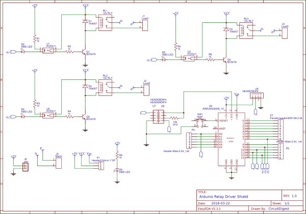
In this 3-Channel Relay Driver Circuit, we have used an optocoupler to trigger the NPN transistor which further drives the relay. And optocoupler will be triggered by the active LOW signal. Here we have used a 12v 10Amp relay in this PCB board, you can also use 5v relays.
Working and Demonstration:
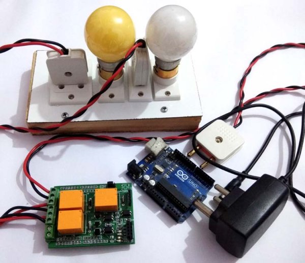
For demonstrating this Arduino Relay Driver Shield, we have used an Arduino Uno board for controlling relays. We have connected all 3 relays with Arduino at 7, 9, and 12 pins (RLY1, RLY2, and RLY3). We have used a 12v adapter for powering the circuit. Then we have connected 220VAC bulbs at the terminal block of the PCB board and AC supply is also applied to the board. Check the Demonstration Video at the end of this project.
Complete Arduino code is given at the end of this project, code is simple and easily understandable. If you want to learn more about Relay and its interfacing with Arduino then follow this link.
You just have to fix the Arduino shield over Arduino and control 3 Appliances using this shield. You can use the given code (in the end) or use your own code for controlling the AC appliaces.
Circuit and PCB Design using EasyEDA:
To design this Arduino Relay Shield, we have chosen the online EDA tool called EasyEDA. I have previously used EasyEDA many times and found it very convenient to use since it has a good collection of footprints and it is open-source. After designing the PCB, we can order the PCB samples by their low cost PCB fabrication services. They also offer component sourcing service where they have a large stock of electronic components and users can order their required components along with the PCB order.
Read more: DIY Arduino Relay Driver Shield
- How many AC appliances can this shield operate?
You can operate 3 AC appliances at a time. - What voltage relays are used in this PCB board?
The project uses a 12v 10Amp relay, though 5v relays can also be used. - Which Arduino pins are used to connect the relays?
All 3 relays are connected to Arduino pins 7, 9, and 12. - Can I order the PCB without building it myself?
Yes, you can order the PCB samples directly from JLCPCB fabrication services. - Does the circuit use isolation for safety?
Yes, the design includes an isolated PCB that uses an optocoupler to trigger the NPN transistor. - What tool was used to design the PCB layout?
The online EDA tool called EasyEDA was chosen to design the Arduino Relay Shield. - How is the optocoupler triggered in this circuit?
The optocoupler is triggered by an active LOW signal. - What power supply is recommended for demonstration?
A 12v adapter is used for powering the circuit during demonstration.
