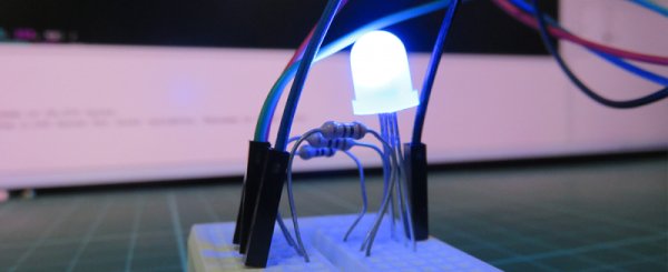
In this project, we will learn how to control the brightness and colour of an RGB LED via I/O ports with PWM output capability, and a touch display sliders. The 4Duino resistive touch display is used as a means for a graphical interface to control the intensity and colour of the RGB LED.
RGB LEDs are essentially three different LEDs combined into one to produce various shades of colours. These LEDs have four legs. The longest leg is the common anode or cathode, and the other three legs represents the colour channel of red, green or blue.
To control colours on an RGB LED we would use pulse width modulation, or PWM for short. Pulse width modulation works by giving the appearance of a “varying analogue voltage” through changing the percentage of time a HIGH voltage signal would be on in one waveform period.
The lower the duty cycle, the more time a signal will spend at a LOW voltage signal state and vice versa.
HOW IT WORKS
COMPONENTS
- 4Duino
- RGB LED (common cathode is used in this example)
- 3 x 220Ω Resistor
- Jumper cable
- Micro USB cable
IMPLEMENTATION
Step 1: Build
Build the circuit as shown in the following diagram and schematic.
The way in which PWM is applied depends on the type of RGB used. With a common anode RGB LED, the long leg is connected to the supply voltage rail (in our case the 5V pin on the Arduino) while the other three legs are controlled by setting a PWM signal to each. If the duty cycle of the PWM signal is high, the colour channel will be very dim or not turn on at all. Why is that? Because for an LED to glow it needs to have a voltage potential across it, and if our PWM signal have a high percentage for duty cycle, it will spend most of its time having 5V voltage potential on both the anode and the colour channel legs and less time with 5V on the anode and 0V on the colour channels.
Step 2: Program
Workshop 4 – 4Duino Basic Graphics environment is used to program this project.
This project requires the Arduino IDE to be installed, as Workshop calls the Arduino IDE for compiling the Arduino sketches. The Arduino IDE, however is not required to be opened or modified to program the 4Duino.
Read more: RGB LED Colour Control

