
Summary of Arduino: an easier way to work with seven segment displays
This article demonstrates how to simplify programming seven-segment displays by using the 4511 BCD-to-7-segment decoder chip with an Arduino. It explains the binary-to-decimal conversion process, provides a wiring guide for a basic count-up timer, and outlines necessary materials including resistors and a photocell for advanced applications. The project eliminates the need to manually control individual display segments by sending simple four-bit binary values instead.
Parts used in the Arduino Seven Segment Display Project:
- Arduino
- 4511 binary seven segment decoder
- Breadboard/jumper wires
- Protoshield from Adafruit
- 470 ohm resistor
- A to B programming cable
- CDS photocell
- 10K resistor
Ever have trouble programming code for seven segment displays? Well they made the 4511 to make things a whole lot easier. What the 4511 does is takes a 4 digit binary input value (ones and zeros), and converts it to a decimal value on a seven segment display, it’s a really handy chip. In this instructable I’ll show you how to use them with the arduino.
Step 1: Materials
Parts:
1.) Arduino
2.) 4511 binary seven segment decoder
3.) Breadboard/jumper wires
4.) Breadboard of some sort (I used a protoshield from Adafruit)
5.) 470 ohm resistor
6.) A to B programming cable
7.) CDS photocell
8.) 10K resistor
Tools:
1.) Computer
2.) A brain 🙂
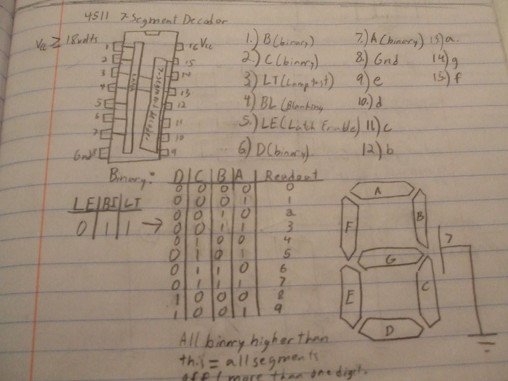
Step 2: How the 4511 works
The 4511 takes a four-bit binary input on pins 1,2,6, and 7. Then translates it to a decimal output when connected to a seven segment display, which means that instead of programming 7 individual pins each time the display changes digits, you only have to program four. Also, instead of finding the exact led’s to turn on for each digit, you just enter a binary value, which leads us to the next step:
Step 3: A thing about binary
For those of you who already are fluent in binary, move on to the next step.
Binary is used in pretty much all mainstream electronics today. It is based on a four digit lines consisting of ones and zeros (each digit is called a bit, each line is called a byte). The first digit in the sequence is equal to one, the second is equal to two, the third is equal to four, and the fourth is equal to eight. So the byte 1001 would be equal to nine (one plus 8). To make it simpler:
Binary: Decimal:
0000 = 0
0001 = 1
0010 = 2
0011 = 3
0100 = 4
0101 = 5
0110 = 6
0111 = 7
1000 = 8
1001 = 9
and so on… (This is as far as the 4511 will go, since it only has one digit capability, it cannot print 10 or up)
Step 4: A simple timer
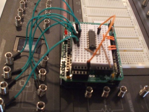
The first thing to do is to build a simple proof of concept circuit, a count up timer, and then go from there, for this, you’ll need to have everything exept the CDS photocell and the 10K resistor.
Step 5: Insert the chip
Insert the chip into the board, make sure to note which way the chip is facing ( where the little notch is o the chip)
2.) 4511 binary seven segment decoder
3.) Breadboard/jumper wires
For more detail: Arduino: an easier way to work with seven segment displays
- How does the 4511 chip simplify programming?
The 4511 takes a four-bit binary input and converts it to a decimal output, requiring only four programmed pins instead of seven. - What is the function of the 4511 chip?
It translates a four-digit binary input value into a decimal value displayed on a seven-segment display. - Which pins accept the binary input on the 4511?
Pins 1, 2, 6, and 7 receive the four-bit binary input. - What is the maximum number the 4511 can display?
The chip can only print numbers up to 9 because it has one-digit capability. - What components are required for the simple proof-of-concept circuit?
You need the Arduino, 4511 chip, breadboard, jumper wires, 470 ohm resistor, and programming cable, excluding the photocell and 10K resistor. - How do you determine the decimal value of a binary byte?
The digits represent values of one, two, four, and eight respectively; for example, 1001 equals nine. - Can the 4511 display numbers greater than 9?
No, the 4511 cannot print 10 or higher as it is limited to single-digit capability. - What tool is needed to upload code to the Arduino?
An A to B programming cable connects the computer to the Arduino for uploading code.