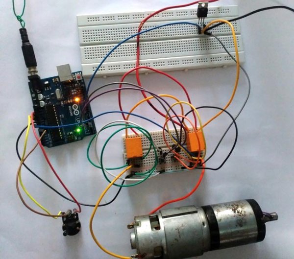
Summary of Arduino DC Motor Speed and Direction Control using Relays and MOSFET
This project uses an Arduino, two relays, a single N-channel MOSFET, two transistors, two pushbuttons, and a potentiometer to control the direction and PWM speed of a 24V DC motor without power switches. Each pushbutton energizes one relay to set motor direction (resembles an H-bridge); the MOSFET handles PWM speed control from Arduino pin 6. Transistors drive the relays from Arduino Vin. Diodes protect against back-EMF. The system prevents rotation when both relays are energized.
Parts used in the Bidirectional Motor Control Project:
- Arduino Uno
- Two 12V relays (5V relays can also be used)
- Two BC547 transistors
- Two pushbuttons
- IRF540N N-channel MOSFET
- 10k resistor
- 24 volt source
- 10K potentiometer
- Three 1N4007 diodes
- Connecting wires
In this project we control direction and speed of a 24v high current motor using Arduino and two relays. No power switches are needed for this circuit, just two push buttons and in Potentiometer to control the direction and speed of DC Motor. One push button will rotate motor clockwise and other will rotate it counter clockwise. One n-channel MOSFET is required to control speed of motor. Relays are used to switch the directions of Motor. It resembles with H-Bridge circuit.
Required Components:
- Arduino Uno
- Two 12v relay( 5v relay can also be used)
- Two transistors; BC547
- Two pushbuttons
- IRF540N
- 10k resistor
- 24 volt source
- 10K potentiometer
- Three diodes 1N4007
- Connecting wires
Circuit Diagram and Explanations:
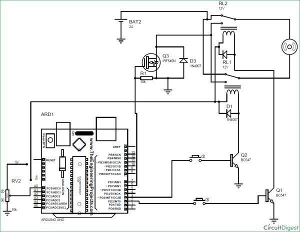
Circuit Diagram of this Bidirectional Motor Control Project is shown in image below. Make the connections according to it:
- Connect normally closed terminal of both relays to positive terminal of battery.
- Connect normally open terminal of both relay to drain terminal of MOSFET.
- Connect source of MOSFET to negative terminal of battery and to Ground pin of Arduino UNO.
- Gate terminal to PWM pin 6 of Arduino.
- Connect 10k resistor from gate to source and 1N4007 diode from source to drain.
- Connect motor in between the middle terminal of relays.
- Out of two remaining terminals, one goes to the Vin pin of Arduino Uno and other to the collector terminal of transistor (for each relay).
- Connect emitter terminal of both transistor to GND pin of Arduino.
- Digital pin 2 and 3 of Arduino, each one in series with pushbutton, goes to base of transistors.
- Connect diode across relay exactly as shown in figure.
- Connect Potentiometer’s end terminal to 5v pin and Gnd pin of Arduino respectively. And wiper terminal to A0 pin.
- ** if you have two separate 12 v battery then connect one battery’s positive terminal to the negative terminal of another battery and use remaining two terminals as positive and negative.
Purpose of Transistors:
Digital pins of Arduino cannot supply the amount of current needed to turn on a normal 5v relay. Besides we are using 12v relay in this project. Vin pin of Arduino cannot easily supply this much current for both relay. Hence transistors are used to conduct current from Vin pin of Arduino to relay which is controlled using a push-button connected from digital pin to base terminal of transistor.
Purpose of Arduino:
- To provide the amount of current required to turn on relay.
- To turn on transistor.
- To control the Speed of DC Motors with Potentiometer using Programming. Check the complete Arduino Code at the end.
![]()
Purpose of MOSFET:
MOSFET is required to control the speed of motor. MOSFET is switched on and off at high frequency voltage and since motor is connected in series with the drain of MOSFET, PWM value of voltage determines the speed of motor.
Current Calculations:
Resistance of relay coil is measured using a multimeter which turn out to be = 400 ohms
Vin pin of Arduino gives = 12v
So current need to turn on the relay = 12/400 Amps = 30 mA
If both relays are energized, current= 30*2=60 mA
**Vin pin of Arduino can supply maximum current = 200mA.
Thus there is no over current problem in Arduino.
Working of Arduino Controlled Bi-directional Motor:
Operation of this 2-way Motor Control circuit is simple. Both pins( 2 , 3 ) of Arduino will remain always high.
When no pushbutton is pressed:
In this case no current flows to the base of transistor, hence transistor remains off ( acts like an open switch) due to which no current flows to relay coil from Vin pin of Arduino.
When one push button is pressed:
In this case some current flows to the base of transistor through pressed push button which turns it on. Now current easily flows to relay coil from Vin pin through this transistor which turn this relay (RELAY A) on and switch of this relay is thrown to NO position. While other relay (RELAY B) is still in NC position. So current flows from positive terminal of battery to negative terminal through motor i.e., current flows from relay A to relay B .This causes clockwise rotation of motor.
When other push button is pressed:
This time another relay turns on. Now current easily flows to relay coil from Vin pin through transistor which turn this relay (RELAY B) on and switch of this relay is thrown to NO position. While other relay (RELAY A) remains in NC position. So current flows from positive terminal of battery to negative terminal of battery through motor. But this time current flows from relay B to relay A. This causes anticlockwise rotation of motor.
When both push buttons are pressed:
In this case current flows to the base of both transistors due to which both transistor turns on (acts like an closed switch). And thus both relay is now in NO position. So current do not flow from positive terminal of battery to negative terminal through motor and thus it does not rotate.
Controlling the Speed of DC Motor:
Gate of MOSFET is connected to PWM pin 6 of Arduino UNO. Mosfet is switched on and off at high PWM frequency voltage and since motor is connected in series with the drain of mosfet, PWM value of voltage determines the speed of motor. Now the voltage between the wiper terminal of potentiometer and Gnd determines the PWM voltage at pin no 6 and as wiper terminal is rotated, voltage at analog pin A0 changes causing change in speed of motor.
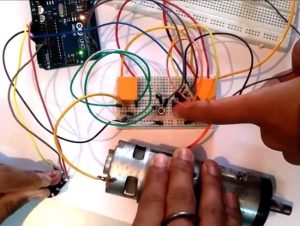
Complete working of this Arduino Based Bi-directional Motor Speed and Direction control is shown in the Video below with the Arduino Code.
Code
int x;
int y;
void setup()
{
pinMode(2,OUTPUT);
pinMode(3,OUTPUT);
pinMode(6,OUTPUT);
pinMode(A0,INPUT);
}
void loop()
{
x=analogRead(A0);
y=map(x,0,1023,0,255);
analogWrite(6,y);
digitalWrite(2,HIGH);
digitalWrite(3,HIGH);
}
Video
Read more: Arduino DC Motor Speed and Direction Control using Relays and MOSFET
- How is motor direction controlled?
Direction is controlled by two relays; pressing one pushbutton energizes its relay to set current flow one way, pressing the other reverses current flow. - How is motor speed controlled?
Speed is controlled by PWM from Arduino pin 6 driving the MOSFET gate; the potentiometer on A0 sets the PWM duty cycle. - Can the Arduino drive the relays directly?
No; transistors (BC547) are used to drive the relay coils because Arduino digital pins cannot supply the required relay current. - What happens when both pushbuttons are pressed?
Both relays switch to NO, creating no current path through the motor, so the motor does not rotate. - Where is the MOSFET placed in the circuit?
The MOSFET drain connects to the relays' NO terminals, the source to battery negative and Arduino GND, and the gate to PWM pin 6. - Why are diodes used in the circuit?
Diodes (1N4007) are used for flyback protection across relays and from source to drain to protect against inductive voltages. - What is the role of the Vin pin of Arduino in this project?
Vin provides 12V to the relay coils through transistors and supplies current required to turn on the relays. - How much current do the relays draw and is Arduino Vin sufficient?
Each relay coil measures about 400 ohms, drawing ~30 mA at 12V; two relays draw ~60 mA, which is within Arduino Vin capability (up to 200 mA).