
Summary of Hookup an LCD to an Arduino
Adding an LCD to Arduino projects often uses many I/O pins; this project uses a 74HC595 shift register to drive an HD44780-style 16x2 LCD using only three Arduino pins plus power. The shield is a small stripboard circuit (minimum 17 strips x 13 holes) including a 74HC595, BC547 NPN, 10k trimmer potentiometer, headers and wiring. Instructions cover stripboard cutting (18 cuts), soldering order, and verification steps to avoid track bridges, enabling a tidy, fast LCD hookup in minutes.
Parts used in the LCD shift-register shield project:
- 1 x 74HC595 Shift Register
- 1 x BC547 NPN (or MOSFET or similar NPN)
- 1 x 10k Trimmer Potentiometer
- 6 x Male headers (right angle suggested)
- 16 x Female headers
- Stripboard / Vero-board (minimum 17 strips x 13 holes)
- Hookup wire
- Soldering kit
Adding an LCD display to Arduino projects can add real value but the cost of doing so can be significant. Not a financial cost – you can pick up 16 (characters) x 2 (rows) LCD for as little as £3.50. The cost is the pin count it can take to drive them. Using the built-in LiquidCrystal Display library it can take as many as 6 pins! That does not leave much for your sensors, motors and other components.
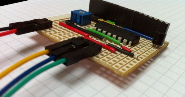
There are many projects that discuss using alternatives – such as a much more expensive Serial LCD (£10 up). Other projects discuss using two-wire interfaces, increasing the complexity of your code. The simplest way to drive the HD44780 style LCDs, in my opinion, is to use a 74HC595 shift register, taking the pin count down to 3.
In any case, connecting an LCD either using the 595 Shift Register or the more traditional way takes a lot of wiring which is not only a super mess (unless you use a ribbon cable I guess), it takes time.
This shield is simplifies this process – all that is required is power and three wires back to the Arduino – ie. connect the LCD in under 6 seconds!
Step 1: Required Components
This is an extremely easy board to make and should take you no more than 15 minutes to solder up and have running.
Component List
1 x 74HC595 Shift Register
1 x BC547 NPN (or MOFSET or similar NPN)
1 x 10k Trimmer Potentiometer
6 x Male headers (I used right angle connectors)
16 x Female headers
Strip/Vero-board 17 strips x 13 holes (I used 15 for cable support)
Hookup wire
Your soldering kit
Step 2: Stripboard Preparation
!! Remember, you are cutting the other side of the breadboard so you need to cut the INVERSE of these graphics. A simple way to get this right is to download the image, flip it horizontally then use it as your cutting guide. !!
There are 18 cuts in total you need to make on your stripboard.
To cut the tracks of these boards you can use a “track cutter” which is available from most electronic component retails, use a drill bit or knife to cut across them or bring out your trusty Dremel and use one of the myriad of tools they have for doing this.
The board size needs to be, at minimum, 17 strips x 13 holes. That said, I used 15 holes to give my cables some extra support.
Double check all track cuts for bridges!
Step 3: Soldering Components
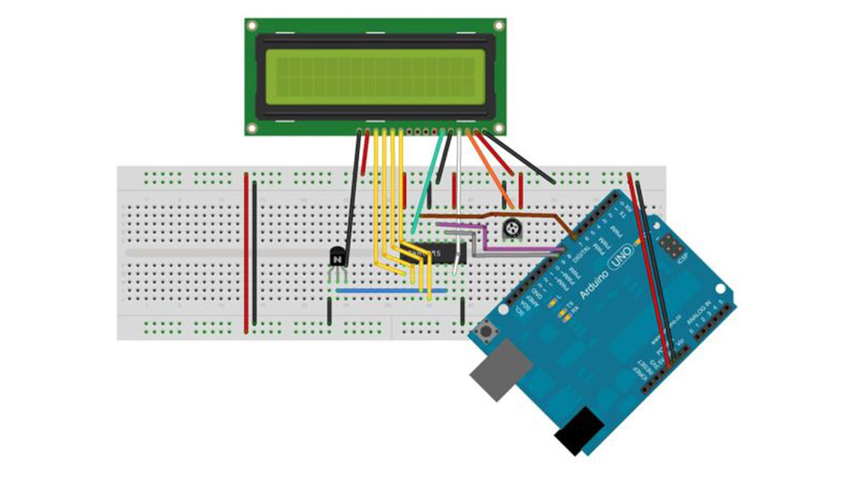
Now comes the fun part of soldering all the components. The attached images will help you place each of the wires and components easily. These are “top-view” images, i.e. your board should look exactly the same from above.
Start by soldering the wires first.
Then the 74HC595 Shift Register, Potentiometer then the NPN.
Lastly, solder in the headers.
The NPN collector pin has been bent backwards slightly and is placed behind the base pin. This is easily seen in the second image.
Double check all track cuts again and your soldering for bridges!
1 x BC547 NPN (or MOFSET or similar NPN)
1 x 10k Trimmer Potentiometer
For more detail: Hookup an LCD to an Arduino
- What is the main purpose of this shield?
To allow connecting an HD44780-style 16x2 LCD to an Arduino using a 74HC595 shift register and only three signal wires plus power. - How many Arduino pins does this setup use?
It reduces the pin count to three Arduino pins for driving the LCD. - Which shift register is used in the project?
The 74HC595 shift register is used. - What transistor is recommended for the design?
A BC547 NPN is used (or a similar NPN or MOSFET alternative). - What size of stripboard is required?
Minimum board size is 17 strips x 13 holes (the builder used 15 holes for cable support). - How many track cuts are needed on the stripboard?
There are 18 cuts required on the stripboard. - What is the recommended soldering order?
Solder the wires first, then the 74HC595, then the potentiometer, then the NPN, and finally the headers. - Why bend the NPN collector pin?
The NPN collector pin is bent back slightly and placed behind the base pin as shown in the instructions for correct placement. - What should be checked after cutting tracks and soldering?
Double check all track cuts for bridges and inspect soldering for bridges.
