
Summary of Making A Pickit 3 Clone
This article details the creation of a custom PICkit 3 clone for programming and debugging Microchip 32-bit processors. Unlike previous hand-wired prototypes, this project utilizes surface mount components on a purpose-designed PCB for a sleeker, modular design. The author developed a new schematic based on existing blog posts and official Microchip documentation, incorporating specific ICs to handle voltage regulation, level shifting, memory storage, and target power control.
Parts used in the Custom PICkit 3 Clone:
- PIC24FJ256GB106 MCU
- Capacitors
- 12MHz Crystal
- USB Connector
- Status LEDs
- OTG Button connections
- MCP1727 Voltage Regulator
- LTC4411 Power Control Circuit
- MAX893L Power Control Circuit
- MCP601 Op-amp
- Voltage Boosting Circuitry
- MCP1525 Voltage Reference Chip
- Target Programming Header
- Three 74LVC1T45 Voltage Level Shifters
- 25LC256 EEPROM
- SST25VF040B Serial Flash Chip
After using the Microchip tools to program and debug the projects I work on, I wondered about creating my own programming/debugging module that I could put on my own boards – just like Microchip does with their starter kits and such. As I became more interested in that idea, I began to search the web to see if anyone else had already done something similar. Initially, I found lots of posts regarding the 2nd version of the Pickit – the Pickit 2, but not as much regarding the latest version – the Pickit 3 – which is what I need to program the 32 bit pic processors that I am using. After a while I came across a post – From this blog
This Individual had created his own version of the Pickit 3 and had posted his method for doing so. I was excited to see some real information about the process, and set about determining how I would do the same, now that I knew someone else had verified that it would work.
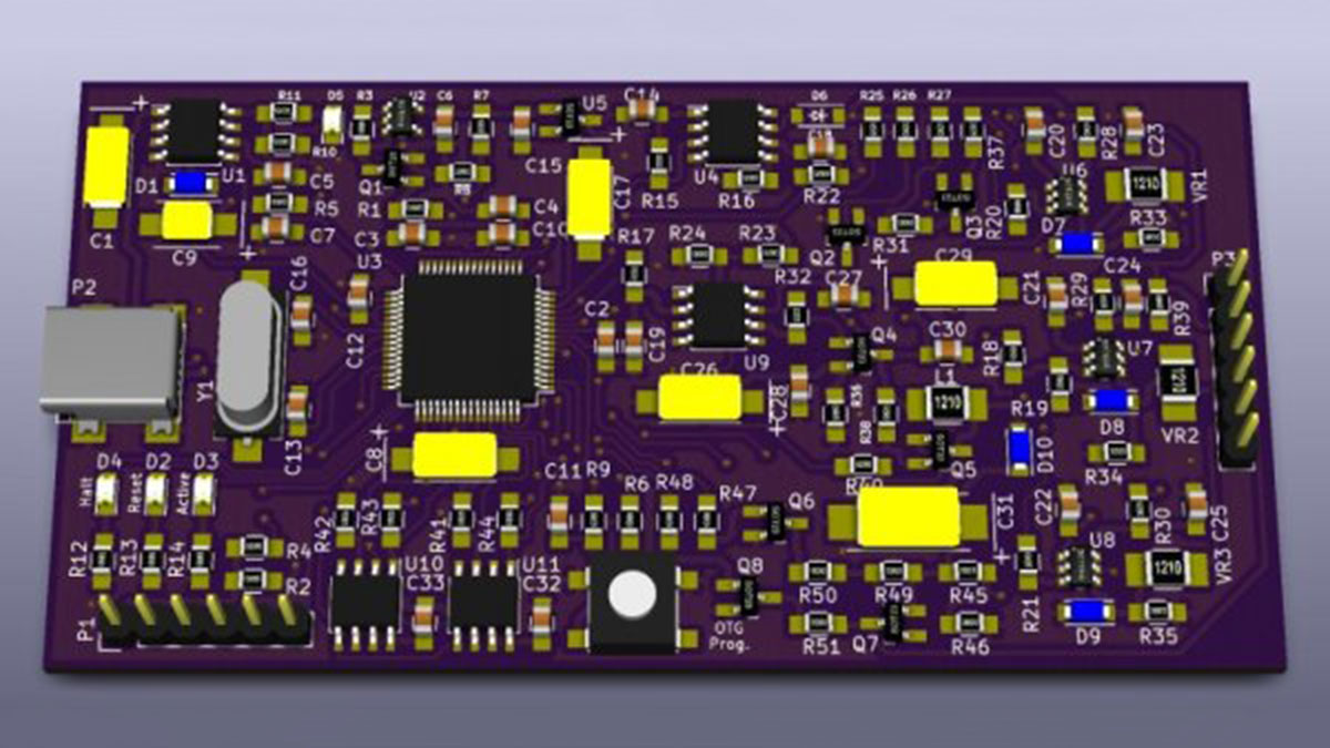
The version that was built on the blog linked above, was done so on a protoboard using a variety of components, and was completely hand-wired. As impressive as that is, I was looking for something a bit sleeker – especially since I was looking at some point to modularize it and use it on other designs. I decided that I would design my project to use surface mount components and a purpose designed PCB. With that in mind, I set out to create my schematic. After looking at the one from Hendrik’s blog post above, and also studying the actual Microchip pickit 3 schematics that are publicly available in the documents released by Microchip, I came up with the following schematic. It is pictured below, and here is a link to the full-sized PDF: My Schematic
This schematic is very similar to the one Hendrik used, with a couple component changes and a fix for a PNP transistor that was shown backwards on his schematic. I’ll briefly talk about the different sections that I have labeled above. First – in the upper left corner is the pic24 processor that controls this device. It is a PIC24FJ256GB106 mcu. There are the requisite capacitors and 12MHz crystal attached, as well as a programming header to load its firmware. In addition to these components, the USB connector is shown, as well as the status LEDs and OTG Button connections. Directly below the MCU is the MCP1727 voltage regulator. At the bottom is a LTC4411, a MAX893L, and associated circuitry that among a couple other things, controls the power to the programming target, if it is not self-powered, and this device is supplying power to it. Above that is a MCP601 op-amp and voltage boosting circuitry. In the middle of the page is a MCP1525 voltage reference chip and the Target programming header. Top center you will see the three 74LVC1T45 voltage level shifters, and to the right are the 25LC256 EEPROM and also the SST25VF040B serial flash chip used for the Code image when doing OTG programming.
Read more: Making A Pickit 3 Clone
- Why did the author decide to create their own programming module?
To have a programmable and debuggable module that could be placed directly on their own boards similar to Microchip starter kits. - What version of the Pickit was the author specifically looking for?
The Pickit 3 is needed because it supports programming the 32 bit pic processors the author uses. - How does the author's design differ from the prototype found on the linked blog post?
The author chose surface mount components and a purpose designed PCB instead of using a protoboard with hand-wired components. - What processor controls the device in the new schematic?
A PIC24FJ256GB106 mcu located in the upper left corner controls the device. - Which chip is used for the Code image when doing OTG programming?
The SST25VF040B serial flash chip is used for the Code image during OTG programming. - What function does the LTC4411 and MAX893L circuitry serve?
This circuitry controls the power to the programming target if it is not self-powered and supplies power from this device. - How many 74LVC1T45 voltage level shifters are included in the design?
The design includes three 74LVC1T45 voltage level shifters located at the top center. - What fix was applied to the schematic compared to Hendrik's original post?
A fix was made for a PNP transistor that was shown backwards on his schematic.
