
Summary of 3.5A Unipolar Stepper Motor Driver
This compact unipolar stepper motor driver utilizes the STK672-440BN IC to control 2-phase motors with up to 3.5A current and a voltage range of 10V to 50V DC. It features PWM current control, micro-stepping capabilities, and comprehensive protection against overcurrent, overheating, and open circuits. The board supports 5, 6, and 8-wire unipolar motors and includes adjustable current settings via a trimmer potentiometer.
Parts used in the Compact Unipolar Stepper Motor Driver:
- STK672-440BN IC
- LM317 (IC U2)
- LED D1 (Excitation Monitor)
- LED D3 (Power LED)
- LED D2 (Fault Indicator)
- Resistor R7
- Capacitor C4
- Trimmer Potentiometer
- Current Detection Resistor (0.122Ω)
- Connector CN1 (Supply Input)
- Connector CN2 (Control Interface)
- Connector CN3 (Stepper Motor Connection)
Compact Unipolar stepper motor driver can drive unipolar motor up to 3.5A and supply range 10 To 50V DC. This compact board is based on STK672-440BN IC from ON semiconductor. The STK672-440BN is a hybrid IC for use as a unipolar, 2-phase stepper motor driver with PWM current control with Micro-stepping.
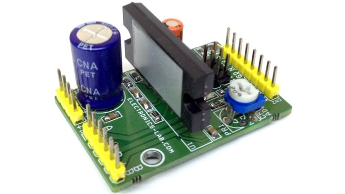
Note: This Board can work with motor supply up to 36V DC, for 50V DC Supply Remove IC U2 LM317, and provide 5V Logic supply from external source. Default Enable pin is High for normal operations, pull down 0 to disable the operations, for internal Power on Reset R7 is 0E , C4 can be omit or its fine as it is.
D1 LED : Excitation Monitor ( Motor Pulse Indicator)
D3 LED : Power LED
D2 LED : Fault Indicator When Over Current, Over Heat, and Motor wires open
CN2 : 1 Pin 5V DC, 2 Pin Direction Put, 3 Pin Clock Input, 4 Pin Enable, 5 Pin Not Connected, 6 Pin Fault 2, 7 Pin GND
CN3 : Stepper Motor Connection
CN 1 : Supply Input ( 10-36V DC) Read Note For Supply 46V Input
Features
- Supply 36V DC (Up to 50V DC See Note)
- Load Current 3.5Amps
- Stepper Motor: 5 Wires, 6 Wires, 8 Wires (Unipolar)
- Built-in motor terminal open detection function, (output current OFF).
- Overcurrent detection function, (output current OFF).
- Overheat detection function (output current OFF).
- FAULT1 signal (active low) is output when any of motor terminal open, overcurrent or overheat is detected.
- The FAULT2 signal is used to output the result of activation of protection circuit detection at 3 levels.
- Built-in power on reset function
- A micro-step sine wave-driven driver can be activated merely by inputting an external clock.
- External pins can be used to select 2, 1-2 (including pseudo-micro), W1-2, 2 W1-2, or 4W1-2 excitation.
- The switch timing of the 4-phase distributor can be switched by setting an external pin (MODE3) to detect either the rise or fall, or rise only, of CLOCK input.
- Phase is maintained even when the excitation mode is switched.
- Incorporating a current detection resistor (0.122Ω: resistor tolerance 2%),
- Motor current can be set using Trimmer Potentiometer ( V Ref Range 0.2V-1.8V)
- The ENABLE pin can be used to cut output current while maintaining the excitation mode
Read more: 3.5A Unipolar Stepper Motor Driver
-
What is the maximum supply voltage for this driver?
The board works with a motor supply up to 36V DC by default, but can handle up to 50V DC if IC U2 LM317 is removed and an external 5V logic supply is provided. -
How do I disable the operations on this board?
The default Enable pin is High for normal operations; pulling it down to 0 disables the operations. -
Can this driver support different types of unipolar stepper motors?
Yes, it supports 5 wire, 6 wire, and 8 wire unipolar stepper motors. -
What protections are built into this driver?
It includes built-in functions for motor terminal open detection, overcurrent detection, and overheat detection, which all turn off the output current. -
How is the motor current set on this board?
Motor current can be set using a Trimmer Potentiometer with a V Ref Range of 0.2V to 1.8V. -
Does the driver support micro-stepping?
Yes, it is a hybrid IC that supports PWM current control with Micro-stepping activated by inputting an external clock. -
What does the FAULT1 signal indicate?
FAUL T1 is active low and outputs when any of the following are detected: motor terminal open, overcurrent, or overheat. -
Can I change the excitation mode externally?
Yes, external pins can be used to select 2, 1-2, W1-2, 2 W1-2, or 4W1-2 excitation modes.
