
Summary of MCUXpresso IDE: Blinky the NXP LPC800-DIP Board
This article provides a tutorial for creating a 'blinky' application on the NXP LPC800-DIP board using MCUXpresso IDE and the LPCOpen library. It details the necessary hardware setup, including the specific microcontroller (LPC824M201JHI33), and explains how to program the device via SWD debugging rather than the onboard UART bridge.
Parts used in the Blinky Application:
- LPC800-DIP board (or any other LPC8xx board)
- NXP LPC824M201JHI33 microcontroller
- MCUXpresso IDE V10.0.0 b344
- Micro USB cable
- SWD/JTAG debug probe (such as LPC-Link2)
- LPCOpen library
- Silabs CP2102 UART-USB bridge (onboard component)
- ISP button (onboard component)
During Embedded World 2017 in Nürnberg I was lucky to get a handful LPC800-DIP boards. To get all students who were lucky to get one, here is a tutorial to make that very exciting ‘blinky’ application on that board:
MCUXpresso IDE Series
This article is part of a series to get up to speed using the new NXP MCUXpresso IDE. Published so far are:
- MCUXpresso IDE: Unified Eclipse IDE for NXPs ARM Cortex-M Microcontrollers
- MCUXpresso IDE: S-Record, Intel Hex and Binary Files
- MCUXpresso IDE: Adding the Eclipse Marketplace Client
- MCUXpresso IDE: Importing Kinetis Design Studio Projects
- MCUXpresso IDE: Installing Processor Expert into Eclipse Neon
- MCUXpresso IDE: Terminate and Disconnect a Debug Session
- MCUXpresso IDE: Blinky the NXP LPC800-DIP Board
Outline
This article shows to run a first ‘blinky’ (toggling LEDs on the board) on the LPC800-DIP board using Eclipse (MCUXpresso IDE) and the NXP LPCOpen library.
You need
- LPC800-DIP board or any other LPC8xx board, in that case you will need to change the LED pins in the source code
- MCUXpresso IDE V10.0.0 b344
- Micro USB cable
- SWD/JTAG debug probe like the LPC-Link2
The LPC800-DIP board does not contain a debug interface, but the USB-2-UART bridge which can be used with the FlashMagic (by Embedded Systems Academy) tool to program binaries. As I want to debug my application, I’m not using this tool in this article.
A link to all the project and source files is provided at the end of the article
LPC800-DIP Board
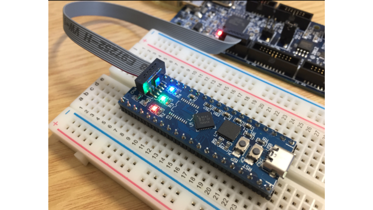
The LPC800-DIP board is a tiny board with the NXP LPC824 microcontroller on it:
It has the LPC824M201JHI33 on it (32 bit Cortex-M0+, 32 KByte Flash, 4 KB RAM) in breadboard friendly pin out. The microcontroller can be programmed using SWD or through the Silabs CP2102 UART-USB bridge: with pressing the ISP button I can program the device through the USB connection to the host and the FlashMagic utility.
SDK: LPC Board and LPC Chip Projects
To start with the board, I need a software library or SDK. For the LPC800 NXP provides the LPCOpen library. That library already is installed with the MCUXpresso IDE:
Read more: MCUXpresso IDE: Blinky the NXP LPC800-DIP Board
-
What is the primary purpose of this article?
The article demonstrates how to run a first blinky application on the LPC800-DIP board using Eclipse and the NXP LPCOpen library. -
Which microcontroller is installed on the LPC800-DIP board?
The board contains the NXP LPC824M201JHI33 microcontroller. -
How can the microcontroller be programmed according to the text?
The microcontroller can be programmed using SWD or through the Silabs CP2102 UART-USB bridge by pressing the ISP button. -
Is a debug interface included on the LPC800-DIP board?
No, the board does not contain a debug interface but features a USB-2-UART bridge instead. -
What software library is required to start with the board?
You need the LPCOpen library, which is provided by NXP for the LPC800 series. -
Does the LPCOpen library come pre-installed with the IDE?
Yes, the LPCOpen library is already installed with the MCUXpresso IDE. -
Can I use a different board besides the LPC800-DIP?
Yes, you can use any other LPC8xx board, but you must change the LED pins in the source code. -
Why was the FlashMagic tool not used in this tutorial?
The author wanted to debug the application, so they did not use the FlashMagic tool which programs binaries via the UART bridge.
