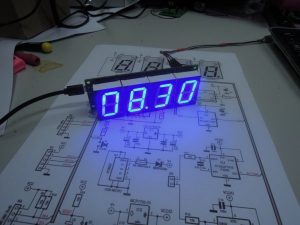
What do you do when you want to design ‘something’ with a vintage or modern display? A clock of course, and this is our first design with RGBDigits: multi-colour 7-segment displays. With a BME280 breakout board attached it will also display temperature, humidity and air pressure. The clock is controlled by an ESP12 module, which makes it possible to synchronise the clock with an internet time server, change the clock settings from any mobile device or computer in the network, or transmit sensor data via Wi-Fi.
RGBDigits are manufactured by a Dutch company with the same name. Every display contains eight 5050 RGB NeoPixel LEDs (seven segments + decimal point) with integrated driver chips, which allow the user to control colour and brightness of every segment/DP individually via a 3-wire bus (VCC, GND an DATA). Up to 10 displays can be daisy chained via their DATA IN and DATA OUT pins.
Each primary colour LED of a NeoPixel can be set to 256 levels of brightness, resulting in 256 x 256 x 256 = 16777216 colours for every segment/DP.
Schematic
The clock is 5V powered via micro USB connector K1. The power supply is protected by 2A PTC resettable fuse F1, Schottky diode D1 serves as reverse polarity protection. IC1 is the main 3.3V voltage regulator, IC6 is the 3.3V supply for the Qtouch touch sensors IC4 and IC5 (separated supply to prevent interference).
The two touch sensors Button0 and Button1 are used to control the display modes of the clock. S1 and S2 are only used for resetting the clock and flashing of the firmware.
IC2 serves as uni-directional level shifter between the 3.3V at the ESP-12E side and the V+ (approx. 4.5V) power supply of the displays.
EEPROM IC3 is used to preserve the clock settings after power off.
A 3.3V FTDI-cable (or other 3.3V USB UART) can be connected to K2 to flash the ESP-12E module, it can also be used for debugging applications.
A BME280 BoB (160109-1) can be connected to K4. The clock will run without it, but of course there will be no sensor data available. An onboard BME280 was no option, heat from the displays will influence the data.
LDR R1 is used to dim the displays in the dark.
K3 makes the 3.3V power and three general purpose I/O pins of the ESP13E accessible for your own developments c.q. future expansions.
Read more: Build A RGBdigit Clock Using Arduino

