
Summary of Intel(r) Quark(tm) micrcontroller D2000 based Environmental sensors board
The Intel Quark D2000 environmental monitoring board is a compact 51x51 mm device featuring a low-power microcontroller and integrated sensors for temperature, humidity, pressure, and acceleration. It supports data storage and transmission via mikroBUS or Grove headers. The design utilizes a 32 MHz clock, an on-chip voltage regulator with external components, and direct battery power for I/O and sensors, enabling efficient environmental data collection and remote processing.
Parts used in the Intel Quark D2000 Environmental Sensors Board:
- Intel Quark D2000 microcontroller (U1)
- Accelerator sensor
- Temperature sensor
- Humidity sensor
- Atmospheric pressure sensor
- 32 MHz quartz resonator (Y1)
- 32768 Hz quartz resonator (Y2)
- 47 uH inductor (L1)
- 4.7 uF capacitor (C11)
- Ferrite EMI filter (FB1)
- Capacitor C7
- CR2032 battery (BT1)
- Resistor R4
- Capacitor C1
- Reset switch (SW1)
- FTDI compatible header (P2)
- mikroBUS compatible header
- Grove compatible connectors
Introduction
This is a fairly small (51 x 51 mm) board, equipped with a low power Intel Quark D2000 microcontroller, and several sensors (accelerator, temperature, humidity, atmospheric pressure), as well as a mikroBUS compatible header and a Grove compatible connectors, that can be used to connect additional sensors, memory, or radio modules. The board can be used to monitor the environment conditions, and store or transmit the data to a remote system for further processing.
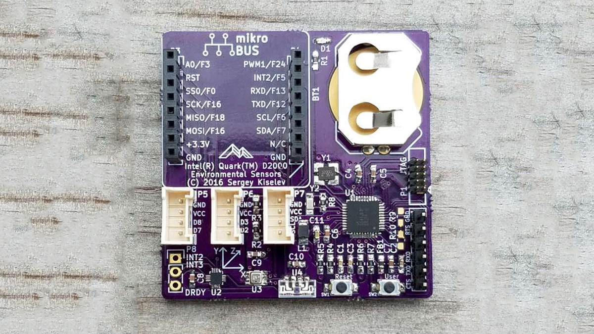
Design Overview
Microcontroller
Microcontroller Overview
The board uses the Intel Quark D2000 microcontroller (U1). This microcontroller contains a 32-bit x86 processor core, 25 GPIOs, I2C, SPI interfaces, JTAG, two UART interfaces, PWM module, timers, and so on. It includes 32 KiB of the instruction Flash ROM, 8 KiB of the SRAM, and a few kilobytes of the OTP memory (which is actually a Flash ROM which can be write/erase protected).
Clocks
The microcontroller runs on a 32 MHz clock provided by quartz resonator Y1, it also uses a 32768 Hz quartz resonator Y2 for RTC clock.
Power Supply
The microcontroller includes an on-chip 1.8V buck converter voltage regulator to supply voltage for the CPU core. The 47 uH inductor L1 and the 4.7 uF capacitor C11 are the external components used by the voltage regulator. The ferrite EMI filter FB1 and the capacitor C7 form an LC filter for filtering the analog supply voltage AVDD. The I/O power supply IOVDD rail, as well as all the on-board sensors are connected directly to the CR2032 battery BT1 (nominally 3V). All the power supply rails are bypassed using 1 uF capacitors.
Reset
The board uses a simple RC reset circuit implemented using the resistor R4, the capacitor C1, and reset switch SW1. The Quark D2000 MCU has a hysteresis on RST_N input, which ensures the proper reset signal generation using an RC circuit.
GPIO Pins Allocation
The GPIO pins of the Quark D2000 MCU are allocated on this board as shown in the table below. Note that GPIO pins have multiple functions (modes), and they need to be configured in the software according to the function used by this board. The suggested pin functions are marked with italic bold.
UART Interface
The UART interface A of the Quark D2000 is exposed on an FTDI compatible header P2. Normally this is used to connect the FTDI USB to serial cable to provide a debug output. The UART interface A TXD and RXD signals are also available on the mikroBUS header, and that can be used to connect sensors that use UART interface.
-
What is the primary function of this board?
The board monitors environmental conditions like temperature, humidity, and pressure, storing or transmitting data to a remote system. -
How does the microcontroller run its clock?
It uses a 32 MHz quartz resonator Y1 for the main clock and a 32768 Hz quartz resonator Y2 for the RTC clock. -
Can additional sensors be connected to this board?
Yes, it features mikroBUS and Grove compatible connectors to link extra sensors, memory, or radio modules. -
What powers the I/O rails and on-board sensors?
All I/O power supply rails and onboard sensors are connected directly to the CR2032 battery BT1 which nominally provides 3V. -
How is the reset signal generated on this board?
A simple RC reset circuit using resistor R4, capacitor C1, and reset switch SW1 generates the signal, supported by MCU hysteresis. -
What is the purpose of the FTDI compatible header P2?
It exposes UART interface A signals typically used to connect an FTDI USB to serial cable for debug output. -
Does the microcontroller have multiple GPIO functions?
Yes, GPIO pins have multiple modes and must be configured in software according to the specific function used. -
Which interfaces are available on the mikroBUS header?
The mikroBUS header includes UART interface A TXD and RXD signals for connecting sensors that use the UART interface.
