
Summary of Circuit delivers constant power to a load
This article describes a circuit that regulates power to variable-resistance loads by generating constant-energy pulses. Instead of controlling voltage or current, the system adjusts pulse frequency to vary total power. It details methods to charge and discharge a capacitor through the load, addressing efficiency issues in simple designs and optimizing energy delivery using threshold-based charging to minimize overshoot. The implementation utilizes a 555 timer for switching and logic control.
Parts used in Constant Power Load Regulator:
- Capacitor C
- Load resistor RL
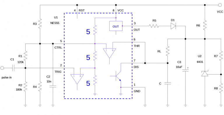
- Resistors R1 and R2
- Coupling capacitor C1 (2-10 pF)
- 555 timer IC
- Comparator
If you have a load with a variable or poorly specified resistance and want to regulate the power applied to it (a heater for example), merely controlling the voltage or current will not work, as in both cases the power P = I2R = V2/R depends on R.
Instead, let us generate pulses with constant energy Epulse, independent of the resistance of the load RL. Then by changing the frequency f of the pulses we can conveniently and precisely control the load power (P = f·Epulse), from 0 to a known maximum level.
Figure 1a shows a simple way to generate a constant energy pulse. Capacitor C is charged to an initial voltage V0, storing ½CV02 joules. It is then discharged through the load. The pulse has a constant energy that does not depend on RL.
Such a simple approach has drawbacks. First, it is wasteful. In order to charge the capacitor with ½CV02 joules, another ½CV02 joules are lost (see Appendix for details). The circuit of Figure 1b fixes that problem – all resistive losses now occur in the load.
One thing to note is that the power distribution of the pulse is quite uneven. About 63.2% of the energy is delivered in the first ½τ (τ = RLC; energy lost in the load evolves twice as fast as the voltage rises, hence the factor ½). It takes a further ½·4τ for the next 36.1% of energy, which is equivalent to only about 1/7 of the average power during the first ½τ. The uneven power distribution limits the maximum power that can be controlled by the circuit. It takes infinity to transfer the remaining 0.67% of the energy. In practice this will be ignored, limiting accuracy.
However, as shown in Figure 1c, we can interrupt charging after the capacitor has reached a certain threshold value, VC. The energy dissipated in the load is equal to CVCV0 – ½CVC2 and is again independent of the value of RL (see Appendix for derivation).
When choosing the value of VC, the main consideration is overshoot, which causes the energy of the pulse to be higher than calculated. The slew rate at the moment the threshold is reached is equal to:
A lower threshold value VC results in higher overshoot for the same comparator speed.
The Design Idea in Figure 2 shows one possible implementation. A 555 provides switches, a comparator, and logic. The trigger input is biased above the trip point by divider R1 & R2. Triggering pulses pass through a small capacitor, C1 (2-10 pF), in order to prevent saturation of the comparator (see 8.3.1 of the datasheet). The maximum operating frequency is therefore comparable to that of an oscillator.
Read more: Circuit delivers constant power to a load
- Why is controlling voltage or current insufficient for variable resistance loads?
Controlling voltage or current fails because power depends on resistance when calculating P equals I squared R or V squared over R. - How does the proposed method control load power?
The method generates pulses with constant energy independent of load resistance and varies the pulse frequency to adjust total power. - What is the main drawback of the simple capacitor discharge approach shown in Figure 1a?
The simple approach is wasteful because half the stored energy is lost during the charging process. - How does the circuit in Figure 1b improve upon the simple design?
All resistive losses now occur in the load rather than being wasted during the charging phase. - What limits the maximum power control accuracy in this circuit?
The uneven power distribution where most energy is delivered early and a tiny fraction takes infinite time to transfer limits accuracy. - How can overshoot be managed when choosing the threshold value VC?
A lower threshold value results in higher overshoot for the same comparator speed, so it must be chosen carefully. - What role does the small capacitor C1 play in the Figure 2 implementation?
The small capacitor prevents saturation of the comparator when triggering pulses pass through it. - What component provides switches, a comparator, and logic in the Figure 2 design?
A 555 timer provides the necessary switches, comparator, and logic functions.
