Summary of Using USB Type-C on hobbyist projects
This article explains implementing USB Type-C on hobbyist projects, covering UFP (device) and DFP/DRP (host) modes. It details resistor configurations for 2.0 compatibility, CC line voltage monitoring for power detection up to 3A, and the use of ICs like TUSB320 for host functionality. The guide excludes complex USB 3.1 multiplexing but notes its availability via specialized chips.
Parts used in the USB Type-C Project:
- 5.1k pull-down resistors
- Type-C receptacle
- Type-C plug or captive cable
- Analog-to-Digital Converter (ADC)
- TUSB320 configuration channel control IC
- USB controller supporting On-The-Go
The new Type-C USB connector is the latest addition to the USB connector standards. It offers reversible plugs, direction independent cables, USB3.1 speeds, and 3A charging in a connector only a little bigger than the USB 2.0 MicroB connector. In order to add these capabilities the plugs and connectors have additional configuration pins to allow devices to negotiate their state. Supporting the configuration channel may seem like a difficult challenge but it can be achieved fairly simply for the basic use cases.

Type-C as a 2.0 device with a type-C receptacle
In this mode the Type-C device is acting as an UFP (Upstream facing port).
This is the equivalent of devices equipped with either a B, Mini-B or Micro-B socket and majority of hobbyist projects will probably fit into this category.
Luckily this is fairly easy to implement as we can avoid worrying about multiplexing or managing connection states.
The simplest implementation of this is to use two 5.1k pull down resistors on the CC lines.
This allows for detection by other devices when using a USB C-C cable.
The USB 2.0 Data lines can both be connected together at the receptacle as only one pair will be populated in the connector.
The power and ground lines will all want connecting to the appropriate power rails on your board.
The Sideband pins and superspeed pins should be left unconnected in this configuration.

Type-C as a 2.0 device with a type-C plug or captive cable
If you wish to have a device plug directly into a Type-C receptacle this can be done much the same as above with a few small differences.
As the orientation of the plug is fixed at your end only one pull-down configuration resistor (5.1k) will be needed (the one attached to A5). This needs to be the correct cc channel as some devices multiplex the USB2.0 data lines.
In addition only one set of USB 2 data pins should be present in the plug (A6 and A7) so there isn’t a need to connect to both pairs like the previous case.
Using Type-C power on devices
If you want to use Type-C power which provides up to 3A at 5V (note: this is different to the USB Power Delivery capabilities) you will need to monitor the voltages at the CC lines to perform power detection. This can be achieved by either using an ADC or using a IC To manage the CC detection for you. Table 4-25 in the USB Spec covers the voltages that represent the power sources capabilities. note: the capabilities of a host may change while connected so this needs to be monitored throughout the connection.
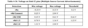
* less than 0.2v nothing is plugged in/the other CC line is connected.
* between 0.2v and 0.66v only default USB power is available.
* between 0.66v and 1.23v 1.5A USB-C power is available.
* above 1.23v 3A USB-C power is available.
note: there are many out of spec legacy cables available that have the wrong CC pull-up resistor, this leads them to advertising the wrong power capabilities of the charger or host.
Type-C as a 2.0 host or dual role device.
Using Type-C as a DFP (downstream facing port) or a DRP (dual role port) is a bit more complicated than the previous example.
This is because the host needs to detect the connection before connecting VBUS to the device.
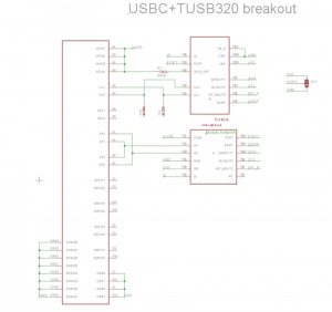
While it would be possible to do this yourself there are configuration channel control ICs available to perform this task such as the TUSB320.
These ICs handle the majority of the work for you.
The bits you are left with are turning on VBUS once connection has been established and putting your device into the correct USB mode.
This is often already provided by your controller if it supports USB on-the-go, many configuration ICs have an ID pin that acts like the ID pin on on the go connector for this reason.
Even if you are using the device in host only mode, you will need to enable VBUS only when a connection has been established to prevent two USB devices attempting to provide power at the same time.
An example schematic using the TUSB320 is shown below.
USB 3.1 operation and USB Power Delivery
While USB3.1 superspeed multiplexing and USB power delivery are outside of the scope of this guide there are ICs available which provide these functionalities however they are often in BGA packages which are difficult to work with.
Read more: Using USB Type-C on hobbyist projects
- How can a Type-C device act as a 2.0 UFP?
Use two 5.1k pull-down resistors on the CC lines to allow detection when using a USB C-C cable. - What is the best way to implement a Type-C plug with a captive cable?
Connect only one 5.1k pull-down resistor to the A5 CC channel and use only one set of USB 2 data pins. - Does the system support 3A charging without Power Delivery?
Yes, by monitoring CC line voltages where values above 1.23v indicate 3A availability. - Can I detect power source capabilities dynamically?
Yes, monitor CC line voltages throughout the connection because host capabilities may change while connected. - What component helps manage CC detection for power?
You can use an ADC or a specific IC to manage CC detection instead of manual voltage monitoring. - How do you prevent power conflicts when acting as a host?
Enable VBUS only after detecting a connection to avoid two devices attempting to provide power simultaneously. - Which IC is recommended for handling host configuration tasks?
The TUSB320 is suggested to handle most configuration channel work for downstream or dual role ports. - Are USB 3.1 features included in this basic guide?
No, USB 3.1 superspeed multiplexing is outside the scope of this guide due to complex BGA packages.