
Summary of Isolated Circuit Digitally Indicates 120-/220-V Line Voltage
This article describes a circuit that detects whether an AC line voltage is 120 V or 220 V. It uses an optocoupler to drive a transistor, producing a low output for 120 V and a high output for 220 V. The design minimizes component degradation by limiting LED current and includes RC filtering to stabilize the signal. The text also notes optional modifications for specific frequency applications and suggests buffering the output for low-impedance loads.
Parts used in the AC Line Voltage Monitor:
- Optocoupler U1
- Resistor R1
- Resistor R2
- Transistor Q1 (2N2222)
- Resistor R3
- Capacitor C1
- Resistor R4
For applications such as motor control or power supplies, it’s often necessary to know whether the ac line is at 120 V or 220 V to adjust the operation. The circuit illustrated in the figure monitors the ac line and provides a basic output indicating whether it is at 120 V or 220 V, with the output at the transistor collector going low for 120-V and high for 220-V inputs.
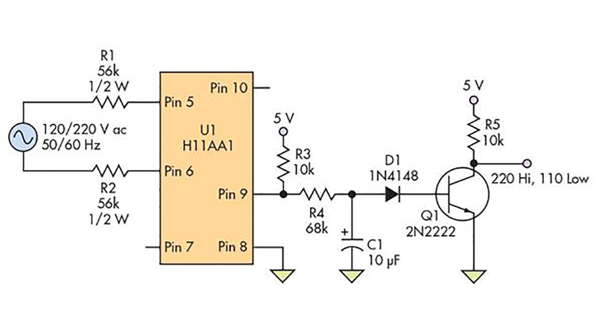
The principle behind the circuit is to make the output of the optocoupler LEDs high enough at 220 V so that it will drive the internal phototransistor to turn transistor Q1 (a standard 2N2222) off to produce a high output, but low enough at 120 V for the phototransistor to turn Q1 on and yield a low output. Optocoupler U1 was chosen because it’s rated and certified for line-voltage applications.
The ac-voltage input goes through resistors R1 and R2 and drives the back-to-back (antiparallel) LEDs inside U1. The LED current, about 1 mA at 120 V and 2 mA at 220 V, is set low to minimize the degradation in current transfer ratio (CTR) over time, which is common with optocouplers (see references). Voltage spikes, which occur at the output of U1 due to the zero crossings where the LEDs aren’t conducting, are narrowest at 220 V as the phototransistor is driven to saturation.
After RC filtering with a 0.7-second time constant, the average voltage isn’t sufficient to turn on Q1; thus, the output is high. Since the current at 120 V is insufficient to fully drive the phototransistor, its output is pulled up by R3 (after filtering by C1/R4) and drives Q1 into saturation. In effect, Q1 is functioning as a low-gain comparator that’s slowly switching between the high and low states at the “don’t care” line voltages of 150 to 170 V, 50/60 Hz.
When the line is at 120 V, there’s short period of about one second at power on when the output will go high and then low, while the capacitor is being charged. This temporary state may need to be ignored, depending on your monitoring circuit. If the 120-V input will always be at 60 Hz, or the 220 V will always be at 50 Hz, and if the monitoring circuit has some time-measuring capability, C1 can be removed. This results in a square wave that can be used to measure the half-period of the ac input (8.33 ms for 120 V and 10 ms for 220 V). Finally, if the output is coupled into a low-impedance load, it’s a good idea to buffer the output with an emitter-follower transistor stage to reduce the loading.
Read more: Isolated Circuit Digitally Indicates 120-/220-V Line Voltage
- How does the circuit distinguish between 120 V and 220 V?
The optocoupler drives the internal phototransistor differently at each voltage, turning transistor Q1 off for a high output at 220 V and on for a low output at 120 V. - What is the function of resistors R1 and R2?
They limit the current through the back-to-back LEDs inside the optocoupler to about 1 mA at 120 V and 2 mA at 220 V. - Why is the LED current set to a low value?
Setting the current low minimizes the degradation in current transfer ratio over time, which is common with optocouplers. - What happens during the power-on period when the input is 120 V?
There is a short period of about one second where the output goes high and then low while the capacitor charges. - Can the circuit be modified to measure AC frequency?
Yes, if the frequency is always 60 Hz for 120 V or 50 Hz for 220 V, removing capacitor C1 creates a square wave to measure the half-period. - How can the output be protected from loading effects?
It is recommended to buffer the output with an emitter-follower transistor stage if it is coupled into a low-impedance load. - What is the role of the RC filter with a 0.7-second time constant?
The filter ensures the average voltage is insufficient to turn on Q1 at 220 V, resulting in a high output state.
