
Summary of DC Output Solid State Relay
This project describes a 10A, 60V DC solid-state relay designed for high-voltage switching without mechanical parts. It utilizes a TLP250/352 opto-coupler gate driver and an IRFP260 MOSFET to achieve fast switching speeds and electrical isolation up to 3750V. The circuit supports dual input methods via anode/cathode or transistor base, operating with trigger voltages ranging from 1.5V to 12V depending on the configuration. A heat sink is mandatory for peak load handling, and specific jumper settings allow for single-supply operation or adjustments for higher voltage inputs.
Parts used in the DC Output Solid State Relay:
- TLP250/352 Opto-Coupler IGBT/MOSFET Gate Driver
- IRFP260 MOSFET
- Opto-isolator
- Solid-state electronic switching device
- Transistor (for signal input)
- Jumper J1
- Jumper J2
- Jumper J3
- Resistor R1
- Resistor R4
- Diode D1 LED
- Heat sink
DC Output Solid State Relay 10Amps 60V DC (Optically Isolated Input)
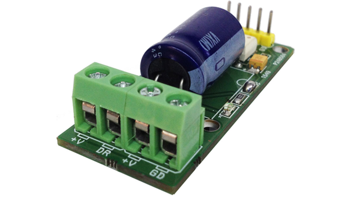
This project has been designed around TLP250/352 which is Opto-Coupler IGBT/MOSFET Gate Driver from Toshiba and Mosfet IRFP260 from IR, This relay consists of optically isolated gate driver and low impedance Mosfet. The combination of low resistance and high load current handling capabilities make this Relay suitable for a variety of switching applications. These devices are ideally suited for controlling high voltage and current DC loads with solid state reliability while providing 3750V isolation from input to output.
A solid-state relay (SSR) is an electronic switching device that switches on or off when a small external voltage is applied across its control terminals. SSRs consist of a Opto-isolator which responds to an appropriate input (control signal), a solid-state electronic switching device which switches power to the load circuitry, and a coupling mechanism to enable the control signal to activate this switch without mechanical parts. This relay designed to switch DC Load up to 10Amps. It serves the same function as an electromechanical relay, but has no moving parts. Solid-state relays have fast switching speeds compared with electromechanical relays, and have no physical contacts to wear out. Input trigger voltage 3V to 9V DC (1.5V to 12 V with Transistor) and output load 10Amps and supply 12V to 60V DC (100V DC also Possible). Gate Driver required supply 12V to 18V DC. Heat sink required for peak load.
Note 1: Q2, R1, J2 Are Optional for Low Current Trigger Signal Input
Note2: J1 (VC-J) Close In Case of Load Supply and Logic Gate Supply are same 12V to 18V DC for single supply input operation
Note 3: Done use R4, D1 LED If Load Supply is higher than 24V DC
Note4: J3 for Cathode ground in case of single pulse input
Features
- +V Supply 60V DC (100V DC Possible) For Load
- VC Supply 12V – 18V DC for Opto-Coupler Gate Driver
- J1 Jumper for Single Supply operations ( If the Load Supply is between 12V DC to 18V DC)
- Load Current Up to 10Amps (Required large size Heat sink for High current Load)
- Two Input Options: 1. Anode Cathode Input 2. Signal input through Transistor Base input
- Input Trigger 3V to 9V DC-Anode and Cathode ( Alter Resistor Value for 24V DC Trigger Input )
- Signal Input 1.5V to 12V DC at Transistor Base ( Alter Base Resister Value for Higher trigger input)
- Isolation Voltage : 3750V ( Gate Driver)
- Operation Input Frequency up to 50Khz ( Refer TLP352 Data Sheet for More info)
Read more: DC Output Solid State Relay
- What is the maximum load current this relay can handle?
The relay is designed to switch DC loads up to 10Amps. - Can this relay operate with a supply voltage higher than 60V?
Yes, the supply voltage can reach up to 100V DC. - How much isolation voltage does the gate driver provide?
The device provides 3750V isolation from input to output. - What are the two available input options for triggering the relay?
The two input options are Anode Cathode Input and Signal input through Transistor Base input. - Is a heat sink required for this project?
Yes, a heat sink is required for peak load conditions. - What is the operating frequency range of the relay?
The operation input frequency goes up to 50Khz. - Can the relay be powered by a single supply?
Yes, using Jumper J1 allows for single supply operations if the load supply is between 12V DC to 18V DC. - What happens if the load supply is higher than 24V DC regarding R4 and D1?
You should not use R4 and D1 LED if the load supply is higher than 24V DC.
