
Summary of Control servo motors with potentiometers and Arduino
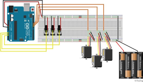
This instructable explains how to control three servo motors using three 10k potentiometers and an Arduino Uno. Potentiometers provide analog input to the Arduino, which maps those values to servo positions; servos are powered from a separate 4xAA battery pack while potentiometers use the Arduino 5V. Grounding between Arduino and battery pack is emphasized. The guide lists required components, breadboard preparation (bridging split power rails), wiring, and software steps for beginners.
Parts used in the Control servo motors with potentiometers and Arduino:
- 3 × 10k potentiometers (breadboard-friendly)
- 3 × micro servo motors
- 4 AA battery pack
- Breadboard
- Arduino Uno R3
- USB cable for Arduino
- Arduino IDE software (to upload sketch)
- Male-to-male jumper cables and jumper wires
- Breakaway header pins
Hi there. This is my first instructable, so I hope you will be patient with me if I make any mistakes setting it up.It is written for beginners like myself, so the more advanced among you can skip a lot of this and just get to wiring it up.
The goal I set myself was to be able to control the robot shown in this web site:
http://bocabearingsworkshop.blogspot.co.id/2015/08…
I needed to be able to control 3 different servo motors by altering the position of 3 potentiometers. There are lots of people out there doing things like this, but I couldn’t find an exact match for everything I needed, so I decided to post up this instructable to bring everything I learned together in one place so that anyone else who wanted to do something like this could get it up and running quickly. This instructable is really a summary of other peoples excellent work and effort.
Before I list out the individual steps involved in this, I want to give a quick explanation of how everything works.
The potentiometers send an analog signal to the Arduino. The sketch on the Arduino (more on this later) then converts the analog input from the potentiometer into a digital output and sends this output to the servo motor which then moves left or right by the appropriate amount.
The potentiometers are powered from the Arduino’s 5v line, while the servos get their power from the battery pack.
Important note: It is VERY important to ground the Arduino into the battery pack/servos to avoid nasty things from happening, but I will talk about this in more detail as we go along.
Step 1: Preparing Your Components
You need three 10k potentiometers with legs that can fit into a breadboard.
I found them here:
https://www.adafruit.com/products/562
Next are the servo motors. I used the smallest ones as the load they would move would be very small and they were cheap.
https://www.adafruit.com/products/169
Next you need a 4 AA battery pack:
https://www.adafruit.com/products/830
A breadboard to connect everything up:
https://www.adafruit.com/products/239
An Arduino Uno R3 (at least this is what I used):
https://www.adafruit.com/products/50
A usb cable to connect the Arduino to a pc and power it:
https://www.adafruit.com/products/62
The Arduino IDE software to upload the program that will control the servos:
https://www.arduino.cc/en/Main/Software
Some male/male jumper cables and some jumper wire to make the connections
https://www.adafruit.com/products/1956
Breakaway header pins which will be used to connect your motors to the breadboard. I like these ones because you don’t have to adjust the plastic divider to get them to fit in a breadboard.
https://www.adafruit.com/products/400
Step 2: Prepare Your Breadboard
A lot of bread boards are split into 2 sections along the power rails at the top and bottom(which caused me a bit of head scratching when I first started using them.) By using 4 small pieces of wire you can bridge across the gap to make sure your power goes all the way across the breadboard. I finally bought one which was connected all the way across but just in case you have this problem, this is how you solve it.
Read more: Control servo motors with potentiometers and Arduino
- What is the goal of this project?
To control three servo motors by adjusting three potentiometers using an Arduino. - How do potentiometers interact with the Arduino?
Potentiometers send analog signals to the Arduino, which converts them and sends appropriate digital outputs to the servos. - Where do potentiometers get power from?
Potentiometers are powered from the Arduino 5V line. - Where do servos get their power from?
Servos are powered from a separate 4 AA battery pack. - Is grounding between Arduino and battery pack necessary?
Yes. It is very important to ground the Arduino to the battery pack/servos to avoid problems. - Why might I need to bridge power rails on a breadboard?
Many breadboards are split along the power rails; bridging with wires ensures power runs across the whole board. - What Arduino board is used in the instructable?
An Arduino Uno R3 is used. - What software is required to upload the servo control program?
The Arduino IDE is required to upload the sketch.
