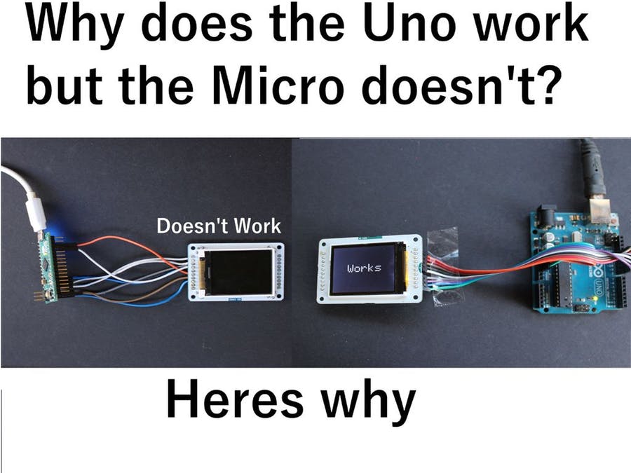
So back when I first started working with micro controllers, Arduinos mainly the most annoying this ever was when i would follow someones tutorial for a project and they would use the Arduino uno, I would be using the Arduino micro or something, i would spend like an hour wiring it up following the instructions piece by piece, get all excited to turn it on and as i do it just straight up doesn’t work – the resulting hissy fits meant a lot of Arduinos lost their lives. Anyway after I calmed down i did some googling and found the cause and a solution which iv used ever since, in this article i hope to explain it to you so hopefully together we can end violence on innocent Micro controllers. Also I have seen looooots of comments asking “can i use the arduino micro instead of uno”
The problem is that occasionally a project will work perfectly fine on an arduino uno but wont work at all on an arduino micro and sometimes a project will work perfectly on both, its the most annoying thing when you spend a tone of time wiring something up and it suddenly doesn’t work for some reason and nothing you can do will get it working so im going to document the steps that will solve this issue most of the time
Step 2: The Differences
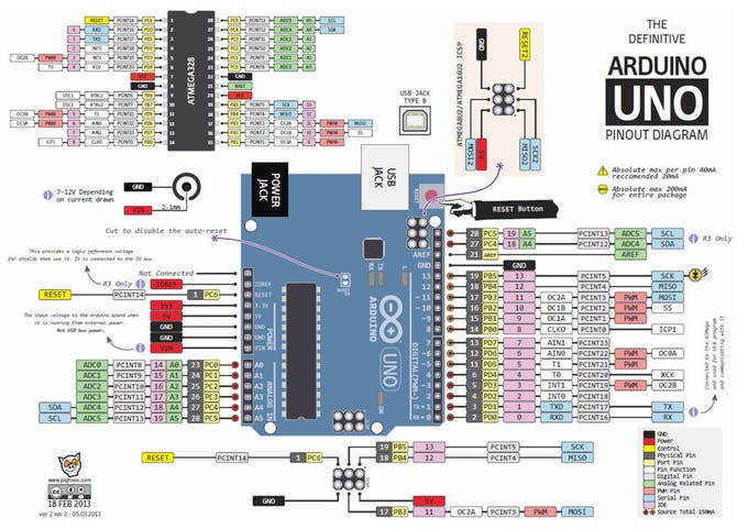
To understand why this problem occurs we need understand that Arduino boards and in fact most micro controllers have something called dedicated pins which perform one function such as the SPI or usb communication.They can be found on the io pins of the board, for example pin A5 on the Arduino Uno is an analogue pin but its also a dedicated scl pin. a lot of the pins also have dedicated functions and this is where our problem arises, lets say the tutorial you are using says plug your component into pin A5 on the Uno so the component can make use of the dedicated scl pin but if you are using the Arduino micro it just wont work because the scl pin isnt on a5 of the micro its on pin 4. Its a bit complicated but if you dont understand it dont worry! You can follow the steps to fix this problem without understanding this.
Step 3: Step 1
first we need to look at the components that you want to use and try and identify any dedicated pins that may be on them they are normally labelled like this (the labels are next to or near the pins)
- SCL (clock line)
- SDA (data line)
- MISO (Master in Slave Out)
- MOSI (Master Out Slave In)
- SS (Slave Select)
- TX (usb communication)
- RX (usb comminication)
if you find none of these and your project still doesn’t work you’re going to need to go find the pin-out of the board the instructions you are following are using and see if the components connects to any dedicated pins if it does it may have just not been labeled on the component and you should move step to, if it isnt connected to a dedicated pin you should check the troubleshooting part of this article.
Step 4: Step 2
Secondly we need to make sure the Arduino we are using has all the dedicated pins that our components need, for example if your components had a SDA, MOSI and MIso pin the Arduino you’re using needs to have those as well you can find this out by googling the board you are using and adding pin-out then just look at images and you should see a list of the dedicated pins, ill add links to the pin-outs of all the most popular Arduino boards
For more detail: Can I Use an Arduino Uno for This?


