
Summary of Arduino Nano: Flame Sensor With Visuino
This tutorial demonstrates building a flame detection system using an Arduino Nano and an Infrared Flame Sensor module. The sensor utilizes infrared light to identify flames, though performance varies in direct daylight versus shadow or night. The guide covers hardware connections and programming the device with Visuino software to read analog values and trigger flame detection.
Parts used in the Arduino Nano Flame Detector:
- Arduino compatible board (specifically Arduino Nano)
- Flame Sensor module
- 3 Female-Female jumper wires
Recently somebody asked for tutorial on Infrared Flame Sensor. It took a while due to severe work overload, but finally I succeeded to make it.
The Infrared flame sensors use infrared light to detect flame. While experimenting with my one I discovered that in direct daylight they don’t work very well due to the infrared component in the daylight. In shadow or at night my one worked quite well. The module that I have has both analog and digital output from a built in comparator.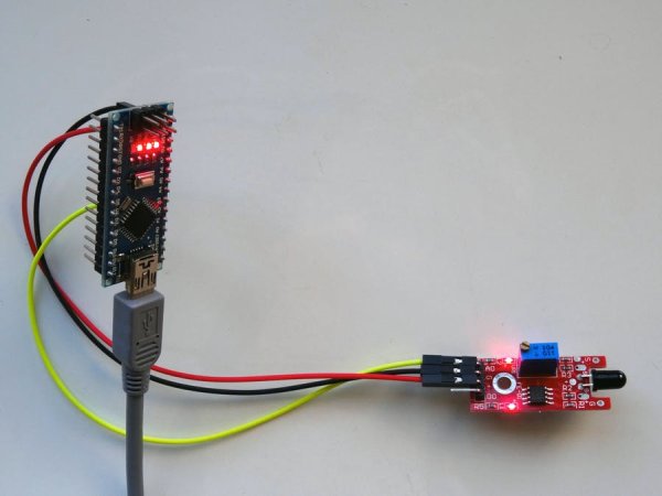
In this tutorial, I will show you how easy it is to connect the Infrared Flame Sensor module to Arduino Nano, and program it with Visuino, to read the values from the sensor, and detect flame.
Step 1: Components
- One Arduino compatible board (I use Arduino Nano, because I have one, but any other will be just fine)
- One Flame Sensor module (I got my one from this cheap 37 sensors set ).
- 3 Female-Female jumper wires
Step 2: Understand the Flame Sensor
The Flame Sensor Module has built in LM393 comparator and has both Digital (DO on the Picture) and Analog (AO on the Picture) outputs. It also has a potentiometer that can be used to control the trigger level for the Digital Output.
You can use either the Analog or the Digital output in your projects.
The element on the right on the picture that looks like LED is the infrared flame sensor itself. It detects heat when the heat is placed at front of it (At front of the rounded end.)
Step 3: Connect the Flame Sensor to the Analog 0 pin of Arduino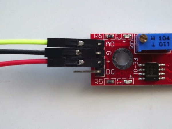
- Connect Ground(Black wire), and Power(Red wire) to the Flame Sensor Module (Picture 1)
- Connect Signal(Yellow wire) to the Analog Pin (AO) of the Flame Sensor Module (Picture 1)
- Connect the other end of the Ground wire(Black wire) to the Ground pin of the Arduino board (Picture 2)
- Connect the other end of the Power wire(Red wire) to the 5V power pin of the Arduino board (Picture 2)
- Connect the other end of the Signal wire(Yellow wire) to the Analog pin 0 of the Arduino board (Picture 2)
- Picture 3 shows where are the Ground, 5V Power, and Analog 0 pins of the Arduino Nano
For more detail: Arduino Nano: Flame Sensor With Visuino
- How does the Infrared flame sensor work?
The sensor uses infrared light to detect flame by identifying heat placed at the front of the rounded end. - Does the sensor work well in direct daylight?
No, it does not work very well in direct daylight due to the infrared component present in daylight. - Can I use either Analog or Digital output?
Yes, you can use either the Analog or the Digital output in your projects. - What is the purpose of the potentiometer on the module?
The potentiometer is used to control the trigger level for the Digital Output. - Which pins are connected to the Flame Sensor Module?
Ground, Power, and Signal wires are connected from the Arduino to the Ground, 5V, and Analog 0 pins respectively. - What software is recommended for programming this project?
Visuino is the software used to program the Arduino and read values from the sensor. - Where should the heat be placed relative to the sensor?
Heat must be placed at the front of the rounded end of the element that looks like an LED. - What specific components are required for the connection?
You need one Arduino compatible board, one Flame Sensor module, and three Female-Female jumper wires.
