Summary of Arduino Irrigation and Plant Watering using Soil Moisture Sensor
This article describes an Arduino UNO-based automatic plant watering system. It monitors soil moisture via a sensor and tank water levels using a float switch, activating a 12V DC motor when conditions require irrigation. The system status is visualized on a 16×2 LCD display with LED indicators for real-time feedback.
Parts used in the Soil Moisture Based Automatic Irrigation System:
- Arduino UNO
- Soil moisture sensor module
- LM393 comparator
- Potentiometer
- Float switch
- 1K Ohm resistor
- Two LEDs
- BC547 transistor
- 12 V DC motor
- JHD162A 16×2 LCD module
This project is about a moisture-sensing automatic plant watering system using Arduino UNO. The system reads the moisture content of the soil using soil moisture sensor and switches ON the motor when the moisture is below the set limit. When the moisture level rises above the set point, the system switches off the pump. The status of the tank, motor and the moisture level will be displayed on a 16×2 LCD display.
So let’s come to our project!
Objectives of the Project
- Monitor the moisture content of the soil using a soil moisture sensor and the water level of the tank using a float switch.
- Turn the motor ON when the soil moisture falls below a certain reference value and if there is enough water in the tank.
- Display the status of the soil and the tank using a 16×2 LCD.
Let’s begin to build our project – Soil Moisture Based Automatic Irrigation System.
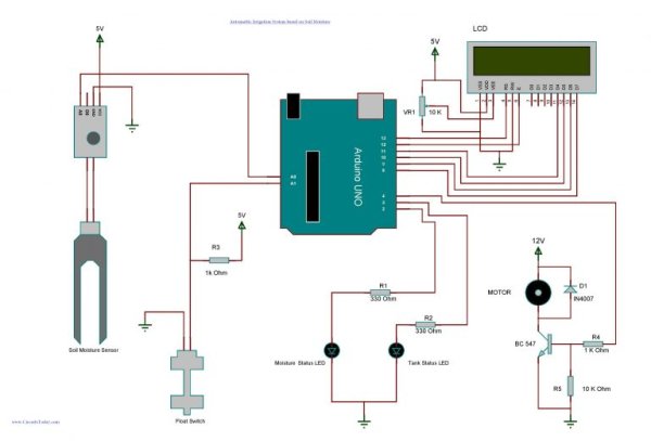
The soil moisture sensor module used here have two output pins ( Digital output and Analog output ). The output from the probe of the moisture sensor is compared with a reference value using a lm393 comparator. The reference value can be changed by turning the potentiometer in the module. The digital pin gives an active low output when the soil is wet. Here we are using the analog output from the module by connecting it to one of the analog pins of Arduino. While using the analog output the wet detection value can be set/adjusted within the program itself.
As shown in the circuit diagram, a float switch is connected to one of the analog pins of Arduino and a 1K Ohm resistor is used to pulled up the line. Analog pins of Arduino can also be used as digital inputs. The status of the tank is identified by checking the output of the float switch. Arduino reads the voltage dropped across the pull up resistor for sensing the level of water in the tank. Two LEDs are connected to the 2nd and 3rd pin of Arduino to show the moisture status and tank status respectively. And the 4th pin links to the base of a BC547 transistor which in turn drives the 12 V DC motor.
A 16×2 LCD is connected with Arduino in 4-bit mode. JHD162A is the LCD module used here. JHD162A is a 16×2 LCD module based on the HD44780 driver from Hitachi. The JHD162A has 16 pins and can be operated in 4-bit mode (using only 4 data lines) or 8-bit mode (using all 8 data lines). Here we are using the LCD module in 4-bit mode. Control pin RS, RW and En are directly connected to arduino pin 13, GND and 12. And data pin D4-D7 is connected to 11, 10, 9 and 8 of arduino.
Read More: Arduino Irrigation and Plant Watering using Soil Moisture Sensor
- How does the system determine when to turn on the motor?
The system switches the motor ON when soil moisture falls below a set limit and there is sufficient water in the tank. - What components are used to monitor the tank water level?
A float switch connected to an analog pin of the Arduino is used to identify the status of the tank. - Can the wet detection value be adjusted within the program?
Yes, when using the analog output from the moisture sensor module, the wet detection value can be set or adjusted in the code. - Which LCD driver chip does the JHD162A module use?
The JHD162A module is based on the HD44780 driver from Hitachi. - How many data lines are utilized when the LCD operates in 4-bit mode?
The LCD module uses only 4 data lines (D4-D7) when operated in 4-bit mode. - Which transistor drives the 12 V DC motor in this circuit?
A BC547 transistor is linked to Arduino pin 4 to drive the 12 V DC motor. - What is the function of the 1K Ohm resistor in the circuit?
The 1K Ohm resistor is used to pull up the line connected to the float switch. - How does the digital output pin of the moisture sensor behave when the soil is wet?
The digital pin gives an active low output when the soil is wet.