Summary of Interfacing 16×2 LCD with Arduino
This article explains the role of display units in embedded systems, focusing on 16x1 and 16x2 LCDs. It details the internal pixel structure controlled by the HD44780 chip and provides a specific wiring guide for interfacing a 16x2 LCD with an Arduino Uno using 4-bit mode to optimize pin usage.
Parts used in the Interfacing 16x2 LCD with Arduino:
- 16x2 LCD Display Unit
- HD44780 Controller
- Arduino Uno
To establish a good communication between human world and machine world, display units play an important role. And so they are an important part of embedded systems. Display units – big or small, work on the same basic principle. Besides complex display units like graphic displays and 3D dispays, one must know working with simple displays like 16×1 and 16×2 units. The 16×1 display unit will have 16 characters and are in one line. The 16×2 LCD will have 32 characters in total 16in 1st line and another 16 in 2nd line. Here one must understand that in each character there are 5×10=50 pixels so to display one character all 50 pixels must work together. But we need not to worry about that because there is another controller (HD44780) in the display unit which does the job of controlling the pixels. (you can see it in LCD unit, it is the black eye at the back ).
To establish a good communication between human world and machine world, display units play an important role. And so they are an important part of embedded systems. Display units – big or small, work on the same basic principle. Besides complex display units like graphic displays and 3D dispays, one must know working with simple displays like 16×1 and 16×2 units. The 16×1 display unit will have 16 characters and are in one line. The 16×2 LCD will have 32 characters in total 16in 1st line and another 16 in 2nd line. Here one must understand that in each character there are 5×10=50 pixels so to display one character all 50 pixels must work together. But we need not to worry about that because there is another controller (HD44780) in the display unit which does the job of controlling the pixels. (you can see it in LCD unit, it is the black eye at the back ).
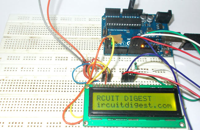
The connections which are done for LCD are given below:
PIN1 or VSS to ground
PIN2 or VDD or VCC to +5v power
PIN3 or VEE to ground (gives maximum contrast best for a beginner)
PIN4 or RS (Register Selection) to PIN0 of ARDUINO UNO
PIN5 or RW (Read/Write) to ground (puts LCD in read mode eases the communication for user)
PIN6 or E (Enable) to PIN1 of ARDUINO UNO
PIN11 or D4 to PIN8 of ARDUINO UNO
PIN12 or D5 to PIN9 of ARDUINO UNO
PIN13 or D6 to PIN10 of ARDUINO UNO
PIN14 or D7 to PIN11 of ARDUINO UNO
The ARDUINO IDE allows the user to use LCD in 4 bit mode. This type of communication enables the user to decrease the pin usage on ARDUINO, unlike other the ARDUINO need not to be programmed separately for using it in 4 it mode because by default the ARDUINO is set up to communicate in 4 bit mode. In the circuit you can see we have used 4bit communication (D4-D7).
So from mere observation from above table we are connecting 6 pins of LCD to controller in which 4 pins are data pins and 2 pins for control.
Read More: Interfacing 16×2 LCD with Arduino
- What is the character capacity of a 16x2 LCD?
A 16x2 LCD has 32 characters in total, with 16 characters on the first line and 16 on the second line. - How many pixels are required to display one character?
Each character requires 50 pixels, calculated as 5 multiplied by 10. - Which controller manages the pixels in the display unit?
The HD44780 controller handles the job of controlling the pixels inside the LCD unit. - How should PIN3 or VEE be connected for best contrast?
PIN3 or VEE should be connected to ground to give maximum contrast, which is best for beginners. - Why is PIN5 or RW connected to ground?
Connecting PIN5 or RW to ground puts the LCD in read mode and eases communication for the user. - Which Arduino pins are used for data transmission in 4-bit mode?
Data pins D4 through D7 connect to Arduino UNO pins 8, 9, 10, and 11 respectively. - Does the Arduino need separate programming for 4-bit mode?
No, the Arduino does not need to be programmed separately because it is set up to communicate in 4-bit mode by default. - How many pins of the LCD are connected to the controller in this circuit?
Six pins of the LCD are connected to the controller, consisting of four data pins and two control pins.