
Summary of Short circuit protection for (almost) any power supply
This project describes a universal short-circuit protection circuit for bench power supplies that uses a low-value series sense resistor and an operational amplifier configured as a comparator to detect overloads via the resistor's voltage drop and switch the supply output accordingly. The design is adaptable to many supplies with simple calculations to choose resistor and thresholds.
Parts used in the Universal Short Circuit Protection:
- Low-value sense resistor
- Operational amplifier (op amp) for comparator
- Reference voltage source or divider
- Power supply rails for the op amp (e.g., +12V and ground)
- Wiring/connectors to place resistor in series with supply output
- Passive components for threshold adjustment (resistors/potentiometer)
- Optional mounting hardware or PCB
Hello, everyone!
This instructable is about a universal short circuit protection that I’ve designed to use in bench power supplies. I’ve designed it to fit in most power supplies circuits. In order to this circuit fit in your bench power supply, you will need to do some calculations, but don’t worry, I’ll explain everything on the next steps.
The circuit is really easy to understand.
A resistor of low value (the resistor value will be explained later) is connected in series with the output of the power supply. As current starts to flow through it, a small voltage drop will appear on it and we will use this voltage drop to determine whether the power supply out put is overloaded or short circuited.
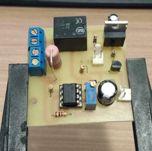
The “heart” of this circuit is an operational amplifier (op amp) configured as a comparator (stage 2).
The way it works is really simple, you just need to follow this rule:
If the voltage on the non-inverting output is higher than the inverting output, then the output is set to “high” level.
If the voltage on the non-inverting output is lower than the inverting output, then the output is set to “low” level.
I put quote marks on “high” and “low” for a easier understanding of the op amp operation. It has nothing to do with logical micro controllers 5 volts levels. When the op amp is in “high level”, its output will be very approximate of its positive supply voltage therefore, if you supply it +12V, the “high output level” voltage will approximate to +12V. When the op amp is in “low level”, its output will be very approximate of its negative supply voltage therefore, if you connect its negative supply pin to ground, the “low output level” will be very near to 0v.
When we use op amps as comparators, we usually have an input signal and a reference voltage to compare this input signal.
So, we have a resistor with a variable voltage that is determined according with the current that flows through it and a reference voltage. Does this ring any bell on your mind? We’re almost finished with the theory be brave and follow me.
For More Details: Short circuit protection for (almost) any power supply
- How does the circuit detect a short circuit?
It measures the voltage drop across a low-value series sense resistor and uses an op amp comparator to compare that voltage to a reference. - Can this protection fit most bench power supplies?
Yes, it is designed to be universal but requires simple calculations to choose appropriate component values for your supply. - What is the role of the op amp in this circuit?
The op amp is used as a comparator to switch its output high or low depending on the sense resistor voltage compared to the reference. - Does the op amp output correspond to logic levels?
No, the op amp output approximates its supply rails (for example near +12V when high and near ground when low), not logic 5V levels. - How is the reference voltage provided?
The reference is provided by a reference voltage source or a resistor divider as described for threshold comparison. - What determines the sense resistor value?
The resistor value is chosen based on calculations relating the desired current threshold and the acceptable voltage drop; details are explained in the article. - How is the sense resistor connected?
The sense resistor is placed in series with the power supply output so the load current produces a proportional voltage drop across it. - What happens when the non-inverting input is higher than the inverting input?
The op amp output goes to a high level approximating its positive supply voltage. - What happens when the non-inverting input is lower than the inverting input?
The op amp output goes to a low level approximating its negative supply voltage or ground.
