
Summary of 2 player Pong using Arduino
This project adapts Kyle Brinckerhoff’s Ardu-pong (original code from Pete Lamonica) into a two-player Pong console using Atari paddles, adding sound and housing the electronics inside an iPhone box. The builder wired video and audio RCA outputs, a 9-pin connector, and connected paddle inputs and buttons to Arduino analog/digital pins, mounted components on wood inside the box, and used resistors to improve video quality.
Parts used in the Ardu-pong Two-Player Pong:
- iPhone box
- Arduino (Freeduino used)
- Atari paddles (2)
- RCA cables/plugs (video and audio)
- 9-pin D connector (RadioShack pn 276-1538)
- RCA cord (old RCA cable)
- 75 ohm resistor
- 1 kohm resistor
- 330 ohm resistor
- 2 10 kohm pull-down resistors
- Wire, screws, small pieces of wood (mounting hardware)
I started with the Instructable from Kyle Brinckerhoff;
http://www.instructables.com/id/Ardu-pong-the-Arduino-based-pong-console/
Thanks Kyle!
and the following at Make magazine
http://blog.makezine.com/archive/2007/08/arduino-pong.html
and I see the original code is attributed to Pete Lamonica
Thanks Pete!!
I am using the paddles instead of the joy stick and I have made it for 2 players. Also I added some sound.
I put the electronics in an Iphone box .
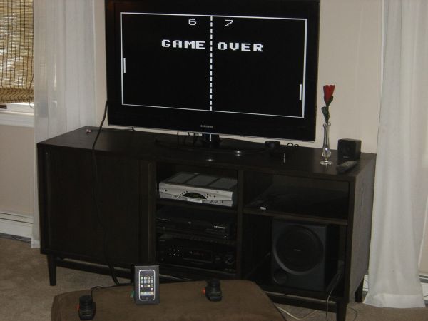
Step 1: Video of the game
https://youtube.com/watch?v=5qqemkZLKiw%3Fhl%3Den%26fs%3D1
Step 2: What I used
I used the following:
Iphone box
Arduino – I had a Freeduino from Solarbotics that I used. The picture shows another but I am sure others would work fine.
Atari paddles – I had from an old system being stored in the basement. I see them on eBay.
An old RCA cord that was in my big box of misc cords
A 9 pin D connector that I got at Radio Shack – pn 276-1538
Also (not shown)
RCA plugs for the cable to attach to – had in my pile of broken things
resistors
75 ohm
1Kohm
330 ohm
2 10k ohm pull down resistors
Some misc hardware – wire, screws,small pieces of wood
Step 3: Prepare the box
I started with a small piece of wood which I cut to fit inside the box. The idea was I would secure everything to this piece and then secure the box to the wood. Holes need to be cut to fit the RCA plugs, the 9 pin connector, and for a USB cable which is needed to attach to Arduino .
I glued another small piece of wood to the larger to be used as a place to secure the Arduino.
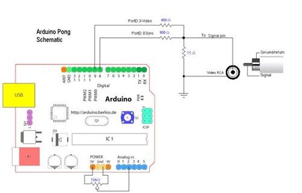
Step 4: Electronics Part1 – the RCA plugs
Following the instructions from Kyle’s Instructable, I soldier a 1k ohm and a 330 ohm resistor to the center pin of the video out RCA jack.
I also connected the 75 ohm that is shown in the diagram . It made the picture a little less bright but much clearer and it stopped a lot of the flickering.
The RCA plug for the sound is straight forward: The center plug goes to Arduino pin 11 and the ground side goes to ground.
The bottom part of the diagram is different than what I did.
Step 5: Electronics Part2 – Connections to Arduino
Basically
Analog pin 1 – goes to paddle 1
Analog pin 2 – goes to paddle 2
Ground – used to ground the 9 pin connector, the RCA connectors
5v goes to the 5 v on the 9 pin connector
Digital pin2 – goes to the button on Paddle 1(button on paddle 2 is not used)
Digital 8 – goes to video RCA
Digital 9 – goes to video RCA
Digital 11 – goes to sound RCA
Arduino
Atari paddles
For more detail: 2 player Pong using Arduino
- Can this project be built using an iPhone box?
Yes, the builder used an iPhone box to house the electronics. - What microcontroller is used in the project?
An Arduino (Freeduino was used by the builder). - How are the paddles connected to the Arduino?
Paddle potentiometers connect to analog pin 1 and analog pin 2; one paddle button connects to digital pin 2. - How is video output implemented?
Video is output via an RCA jack wired to Arduino digital pins 8 and 9 with resistors as described. - How is sound added to the project?
Sound is output through an RCA plug connected to Arduino pin 11 with ground to Arduino ground. - Which resistors are used for the video and why?
A 1 kohm and 330 ohm are soldered to the video RCA center pin and a 75 ohm is added to reduce brightness and flicker and improve clarity. - What connectors are needed to attach to a TV?
An RCA video cable and the RCA video connector assembled as described are used to attach to the TV. - What additional hardware is required to mount components?
Small pieces of wood, screws, and wiring are used to secure the Arduino and connectors inside the box.