Summary of Build Your Own Arduino
This tutorial guides users in building a functional Arduino prototype on a solderless breadboard using an ATmega168 or 328 microcontroller. It details the assembly process, including power regulation with a 7805 chip and capacitors, wiring for constant +5V, and pin mapping for programming. This method allows for quick prototyping without permanent soldering, enabling easy testing of ideas and project modifications.
Parts used in the Breadboard Arduino:
- Solderless breadboard
- ATmega168 or ATmega328 microcontroller chip
- 7805 voltage regulator
- Two 10uF capacitors
- 9V battery with snap connector
- LED status indicator
- 220 ohm resistor
- Hook-up wires (red and black)
Setting up an Arduino on a breadboard has become a process I have grown to love.
Within a few minutes you can have a fully working Arduino platform to work with as you will see in this tutorial. There have been several occasions when I was at school and quickly put together one of these for testing some ideas for a project. Plus it is just looks so neat with all the components laid out over the breadboard.
Whats is an Arduino?
Arduino is an open-source electronics prototyping platform based on flexible, easy-to-use hardware and software. It’s intended for artists, designers, hobbyists, and anyone interested in creating interactive objects or environments.
Arduino can sense the environment by receiving input from a variety of sensors and can affect its surroundings by controlling lights, motors, and other actuators. The microcontroller on the board is programmed using the Arduino programming language (based on Wiring) and the Arduino development environment (based on Processing). Arduino projects can be stand-alone or they can communicate with software on running on a computer (e.g. Flash, Processing, MaxMSP).[1] www.arduino.cc�
Step 1: Components
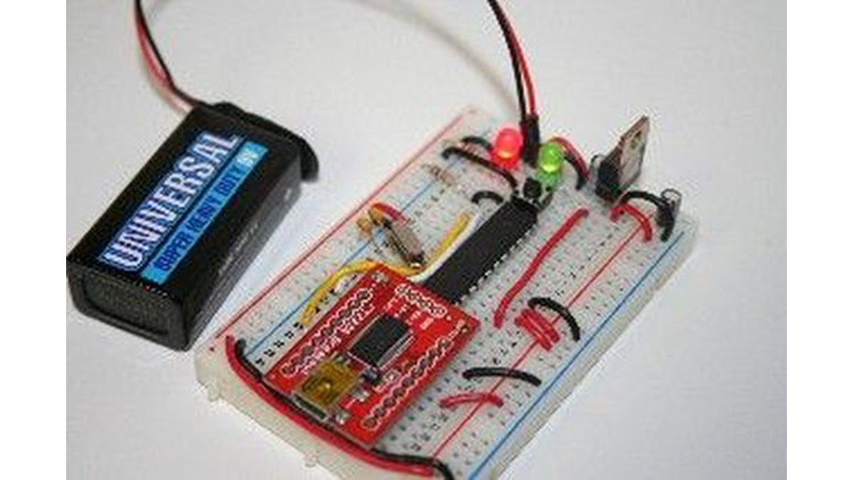
Figure 1-1: Breadboard Arduino with USB programming ability.
* See note about the TTL-232R cable in programming options before purchasing.
10% OFF Entire Order at ArduinoFun.com, use Coupon Code: INSTRUCTABLES upon check out.
You can buy components at www.ArduinoFun.com or www.SparkFun.com or www.CuriousInventor.com or www.FunGizmos.com or www.Adafruit.com just to name a few places off hand.
Origninal tutorial by: http://itp.nyu.edu/physcomp/Tutorials/ArduinoBreadboard
Step 2: Setting Up Power
Figure 1-2: Power setup with LED indicator.
Across the empty space on the breadboard (the channel) you will need to place two hook-up wires for positive (red) and ground (black) to jump power from one side of the breadboard to the other.
Figure 1-3: Left and Right Power Rail Connections.
Figure 1-4: For the LED status indicator, connect a 220& resistor (colored as: red, red, brown) from power to the anode of the LED (positive side, longer leg) and then a GND wire to the cathode side.
Step 3: Arduino Pin Mapping
- How do I set up constant +5V power?
You must use a 7805 voltage regulator powered by more than 5V, such as a typical 9V battery. - What is the correct orientation for the 7805 voltage regulator legs?
When facing the front, the left leg is voltage in, the middle is ground, and the third leg is voltage out. - Can I use the ATmega328 instead of the ATmega168?
Yes, the ATmega328 runs at the same speed with the same pinout but has more flash memory and EEPROM. - Which components are required for the LED status indicator?
You need a 220 ohm resistor connected from power to the LED anode and a ground wire to the cathode. - How do I connect power rails on the breadboard?
Connect positive to positive and negative to negative wires across the bottom to link the left and right power rails. - What software environment is used to program the board?
The board is programmed using the Arduino development environment which is based on Processing.