
Summary of High Speed Photography
This project enables DIY high-speed photography by triggering flashes based on detected movement or sound without modifying the camera. It utilizes a laser barrier sensor and an Arduino to control external flashes, including both old High Voltage and new TTL types. The system allows users to capture fast-moving subjects using affordable components like phototransistors, laser diodes, and the LM317 regulator.
Parts used in the High Speed Photography Trigger:
- Phototransistor / Photodiode
- Resistor (10k)
- LED Laser Diode
- LM317 Regulator
- Arduino Microcontroller
- LCD Display
- Digital Pin 12 Flash Trigger Circuit
- Four Buttons with Pull Down Resistors
With this device you’ll be able to:
take pictures from anything you can sense or detect:
– movement
– sound
– …
You don’t need to modify your camera or flash for this.
It’s compatible with the old High Voltage flashes and the new TTL ones.
 Why I did this project?
A friend of me who’s really passionate about photography showed me some high speed photography examples. And how expensive the equipment you need is.
I said there must be a DIY solution for that and I started tinkering.
We’ve done some experiments and you can see the results in the pictures below.
for more pictures from Sanne
see here http://www.flickr.com/people/sannegovaert/
After following this instructable you’ll be able to make such pictures too!!
What I would do with the zing
If I win the zing laser cutter then my lab is complete, and will I be able to go crazy.
I’ll make: robots, enclosures, front panels, puzzles, build kits, moose heads, etch some cool things
I’ve been waiting a long time to make this instructable so I could join the zing contest and here I’m
Step 1: Laser Trigger (Light barrier) Sensor
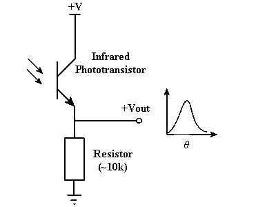
The laser trigger exists of 2 pieces:
-the sensor (this step)
-Laser itself (next step)
See the included pictures for the circuits
You’ll need:
- a phototransistor / photodiode
- just a resistor like 10k
Step 2: Laser driver
Calculate the resistor you need with the following formula
R = 1.25V / Laser Current in A
You’ll need:
- A led laser diode (ebay)
- LM317
- 1 x Resistor
or you can skip the driver and just use a resistor placed in series with the laser diode
Step 3: Build the circuits (Arduino)
You can connect everything to an arduino
Or you can make a pcb (see next step) to do the job so you have your arduino free for other projects
connect your lcd to the arduino see the circuit
connect the output of the sensor circuit to the analog pin 0
connect your digital pin 12 to the flash trigger circuit
connect 4 buttons with a pull down resistor to:
– pin6 (delay+)
– pin7 (delay-)
– pin8 (sens+)
– pin9 (sens-)
You can also make a pcb for this i’ve included the EAGLE files I’ve used
For more detail: High Speed Photography
- How does this device trigger the camera flash?
The device triggers the flash by detecting movement or sound using a laser barrier sensor connected to an Arduino. - Can I use this setup with existing camera flashes?
Yes, it is compatible with both old High Voltage flashes and new TTL ones without needing modification. - What components are needed for the laser driver circuit?
You need an LED laser diode, an LM317 regulator, and one resistor calculated using the provided formula. - How do I connect the buttons to the Arduino?
Connect four buttons with pull down resistors to pins 6, 7, 8, and 9 for delay and sensitivity adjustments. - Is it necessary to build a PCB for this project?
No, you can connect everything directly to an Arduino, though making a PCB frees up the Arduino for other projects. - Where can I find the EAGLE files for the PCB?
The author included the EAGLE files used for the PCB design within the project instructions. - What is the formula to calculate the resistor for the laser driver?
Use the formula R = 1.25V divided by the Laser Current in Amperes. - Can I skip the laser driver and just use a resistor?
Yes, you can skip the driver and simply place a resistor in series with the laser diode.
