
Summary of Hacking Hex Bug Spider using arduino
This article details the modification of Hex Bug Spiders for a Smart Cities exhibition simulation. The author replaces internal electronics to enable control via an Arduino and ZigBee radio, utilizing exposed test points on the IR transmitter for signal routing while preserving two units as controls.
Parts used in the Hex Bug Spider Simulation:
- Hex Bug Spiders (hexapod robots)
- Infra-red transmitter
- AT8EB one chip microcontroller
- ST1155A H Bridge driver
- Arduino board
- ZigBee radio
- Soldering wires
For the Smart Cities exhibition in Leeds in a couple of weeks, we’ve been building a physical representation of an agent based simulation. Hex Bug Spiders are relatively cheap hexapod robots that are controlled via an infra-red transmitter which has an A or B code so that you can control two simultaneously. The way it walks is referred to as the Jamius walking mechanism after its inventor (see: http://www.youtube.com/watch?v=is7x_atNl94 ).
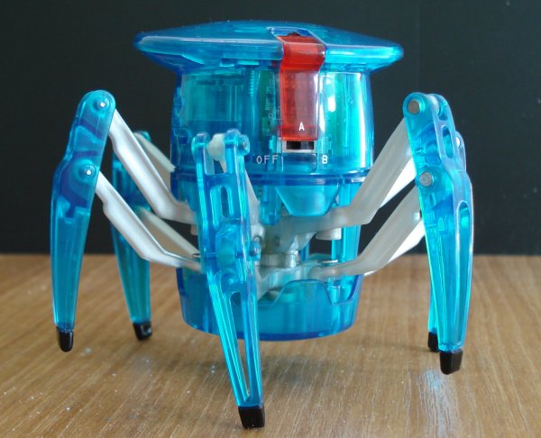 After taking the Hex Bug apart the construction is actually really good for a cheap toy. Both the hand held transmitter and the receiver in the robot are based around the AT8EB one chip microcontroller (Alpha Microelectronics Corp), with the robot itself also containing an ST1155A H Bridge driver. I’ve seen a lot of blog posts about hacking these spiders, but after trying to modify the robot’s control PCB to attach wires to the H Bridge driver directly (as in this blog post: http://www.instructables.com/id/Arduino-Controlled-Hexbug-Spider/), I’ve decided that it’s easier to replace all the electronics rather than hack the surface mount board. Out of the three spiders that I have, I’ve left two robots untouched while the third one has been disassembled. The logic behind this is to modify the IR transmitter and control two via an Arduino attached to a computer, while adding a ZigBee radio to the third for wireless control.
After examining the transmitter PCB, I noticed that there are exposed test points which can be used to attach wires for the forward, backward, left and right switches. I then discovered the following blog post doing almost exactly the same thing:
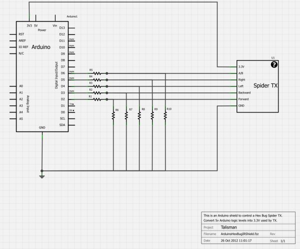 The four test points for the forward, backward, left and right buttons are exposed, so it’s easy to solder on to them. I did have to very carefully remove some of the tape covering the button clickers first though. The A/B switch is very easy to solder to, but the + and – terminals from the battery are covered in hot melt glue which was very difficult to cut away. Then I had seven wires attached to the PCB which I routed through the A/B switch hole on the front case and re-assembled the transmitter. Reading from left to right, the white arrows identify the functions as follows: GND, Forward, +3.3V, Backward, (A/B code bottom with left above it), Right.
For more detail: Hacking Hex Bug Spider using arduino
- What is the walking mechanism called?
The way it walks is referred to as the Jamius walking mechanism. - How can you control two spiders simultaneously?
You can control two simultaneously using an infra-red transmitter with an A or B code. - Why did the author replace all electronics instead of hacking the PCB?
The author decided replacing electronics was easier than modifying the surface mount board to attach wires directly to the H Bridge driver. - Which microcontrollers are found in the transmitter and receiver?
Both the hand held transmitter and the receiver are based around the AT8EB one chip microcontroller. - What components are inside the robot itself?
The robot contains an ST1155A H Bridge driver. - How do you access the switch functions on the transmitter?
You use the exposed test points for forward, backward, left, and right switches after removing tape covering the button clickers. - What makes accessing battery terminals difficult?
The + and - terminals from the battery are covered in hot melt glue which is very difficult to cut away. - What function does the ZigBee radio serve in this project?
The ZigBee radio is added to the third spider for wireless control.